Capillary electrochromatography (CEC) is a miniaturized, hybrid separation technique that combines micro-high-performance liquid chromatography (µHPLC) and capillary electrophoresis (CE). The driving force in CEC is electroosmotic flow (EOF), which is generated by the application of an electric field to a capillary that is usually packed with typical HPLC stationary phase particles (see Figure 1). Column efficiency in CEC is usually much higher than that in HPLC with an identical column, since EOF generates a plug-like flow profile in contrast to the parabolic flow profile in HPLC. Therefore, CEC has both the high selectivity and peak capacity of HPLC and the high efficiency and resolution of CE. In 1974, Pretorius1 successfully used EOF as the driving force through a glass tube packed with a chromatographic stationary phase, which provided column efficiency of about 31,000 N/m. However, CEC had not received much attention until Jorgenson2 separated nonionic aromatic compounds by applying a voltage across a packed capillary column, and Knox3,4 proved high efficiency and other advantages of CEC in theory and practice.
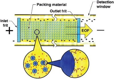
Figure 1 - Schematic of a packed capillary column in CEC.
However, CEC has not become a mainstream separation technique because of the problems and difficulties associated with the lack of proper instrumentation and in-house column fabrication. In addition, the high applied voltage across the column in “pure” CEC format often causes Joule heating, which leads to bubble formation that can result in dryout of the column and disruption of the current.5 Therefore, pressurized CEC (pCEC), or electrokinetic high-performance liquid chromatography (eHPLC), with EOF combining hydraulic pressure as its driving force has gained more attention.6–8
In pCEC, the retention mechanism for neutral compounds is essentially based on chromatographic partition. However, for charged compounds, both chromatographic partition and electrophoretic mobility contribute to the separation mechanism. Therefore, high efficiency, high resolution, high peak capacity, and fast speed separations with pCEC can be achieved. The dual mechanism of pCEC makes it suitable for both neutral and charged compounds and dramatically enhances the separation selectivity compared to a standalone HPLC or CE system. In addition, it is possible to perform pCEC, µHPLC, and CE independently on the same system. Unlike in “pure” CEC, the binary solvent delivery pump provides the capability of gradient elution, and the rotary-type injector in pCEC permits quantitative sample injection. Furthermore, pCEC can be readily coupled with on-column detection schemes such as UV, laser-induced fluorescence (LIF), MS, and electrochemical (EC) detection. Due to its micro-nanoscale feature, pCEC is also economically attractive and environmentally friendly.
This article reports on research and development on pCEC including instrumentation, columns, and applications. The advantages of pCEC in terms of separation efficiency, selectivity, resolution, speed, and peak capacity are demonstrated by the separation of biologicals and pharmaceuticals.
Experimental
Apparatus
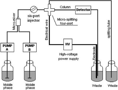
Figure 2 - Schematic of TriSep-2100 pCEC system.
All pCEC experiments were carried out using a TriSepTM-2100 capillary electrochromatography system (Unimicro Technologies Inc., Pleasanton, CA), which consisted of a binary solvent gradient module, high-voltage power supply (±30 kV); microfluidic control module including a six-port injector; workstation; and on-column variable-wavelength UV-VIS or LIF detector. As illustrated in Figure 2, the mixed mobile phases, delivered by the binary solvent delivery system, flow through the six-port injection valve. Sample is injected into the sample loop and is then carried by the mobile phase to the splitting cross, where the grounding electrode is connected. Depending on the split ratio, about 1% of the sample and mobile phase flows into the capillary column. A capillary restrictor or backpressure regulator connected with the splitting cross can control the flow speed in the column and maintain a constant pressure at the inlet of the capillary column to suppress bubble formation. The waste vial contains both the capillary column outlet and the positive or negative electrode. The capillary columns with detection windows were installed into the UV-VIS or LIF detector, which transmitted signals to the chromatographic workstation (Unimicro Technologies).
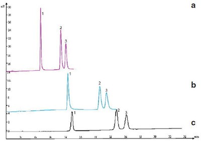
Figure 3 - Separation of three flavone compounds by a) pCEC, b) µHPLC, and c) HPLC. Column—a) and b): 50 cm (effective length 25 cm) × 150 µm i.d. capillary packed with 5 µm C18, and c): 250 mm × 4.6 mm i.d, 5 µm C18. Mobile phase: methanol—15 mM Na2HPO4 (55:45, v/v). Flow rate: a) 500 nL/min, b) 400 nL/min, and c) 1 mL/min. Voltage: a) 10 kV, b) and c) 0 kV. Detector: UV at 360 nm. Peak identification: 1) quercetin, 2) isorhamnetin, and 3) kaempferol.
Reagents and materials
Chromatographic-grade methanol, acetonitrile (Tedia Co. Inc., Fairfleld, OH), and other analytical-grade chemicals (Sinopharm Chemical Reagent Co. Ltd., Shanghai, China) were used. All solutions were filtered using 0.22-µm filters.
Column
Capillaries with 75~150 µm i.d. and 365 µm o.d. (Polymicro Technologies, Phoenix, AZ) were packed electrokinetically9 with, in most cases , 3–5 µm porous octadecylsilica (ODS) particles (Global Chromatography, Su Zhou, China). Detection windows were generated by burning off about 2 mm polyimide coating. Some capillary columns used in this work were packed with 1.5-µm nonporous C18 particles to increase column efficiency and resolution. Exotic stationary materials, such as gold microspheres, can be packed into the capillary column.10
Results and discussion
High-speed separation and high column efficiency
Table 1 - Comparison of column efficiency and retention time between pCEC, μHPLC, and HPLC
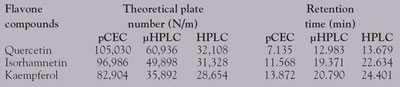
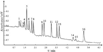
Figure 4 - Separation of 16 PAHs in pCEC. Column: 35 cm (effective length 10 cm) × 100 µm i.d. capillary packed with 1.5 µm NPS C18. Mobile phase A: 2 mM Tris H2O, B: 2 mM Tris acetonitrile. Gradient: 0~2 min, 50~75%B. Flow rate: 400 nL/min. Voltage: 30 kV. Detector: UV at 254 nm. Peak identification: 1) naphthalene, 2) acenaphthylene, 3) acenaphthene, 4) fluorene, 5) phenanthrene, 6) anthracene, 7) fluoranthene, 8) pyrene, 9) benz[a]anthracene, 10) chrysene, 11) benzo[b]fluoranthene, 12) benzo[k]fluoranthene, 13) benzo[a]pyrene, 14) dibenz[a,h]anthracene, 15) benzo[ghi]perylene, 16) indeno-[1,2,3-cd]pyrene.
The major advantage of pCEC is its high efficiency and fast speed due to its combined driving force, i.e., EOF and pressure. Flavone compounds widely exist in many traditional Chinese medicines. Although they can be separated and detected by HPLC, µHPLC, and pCEC, as shown in Figure 3, a much higher theoretical plate number was obtained using pCEC rather than µHPLC and HPLC. In addition, the retention time of flavone compounds separated by pCEC was nearly only half of the retention time in HPLC under similar pressure. The column efficiency and retention time in the three separation modes are listed in Table 1. The pCEC system makes the separation speed much faster with application of the dual mechanism and small particles. For example, 16 polycyclic aromatic hydrocarbon (PAH) components were baseline separated within 6 min, as demonstrated in Figure 4.