As the science of HPLC has evolved over the years, we have witnessed many changes to HPLC chemistry and instrumentation. With reductions in particle size from 10 μm, 5 μm, and then to 3.5 μm, and with reductions in column geometry, analytical resolution has increased and run times have become shorter. The landscape really changed, however, with the introduction of sub-2-μm particles in the early part of the last decade. Along with improved resolution, sub-2-μm particles extend the effective linear velocity range (flow rate/column diameter) and have led to dramatic improvements in speed. Figure 1, known as the van Deemter curve, explains the phenomenon.
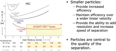
Figure 1 - van Deemter curve.
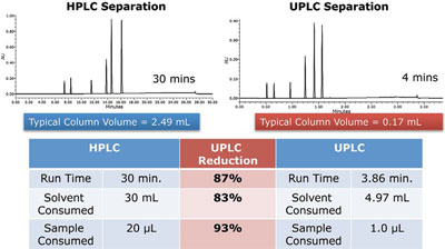
Figure 2 - Gradient method transfer example.
In 1956, Jan Josef van Deemter demonstrated the relationship between particle size and efficiency represented by linear velocity to determine the optimal flow rate for the highest resolution. Under this scenario, efficiency is proportional to the inverse of particle size. As seen in Figure 1, optimal linear velocities for each size HPLC particle are represented. For a 1.7-μm particle, the “sweet spot” for flow rate is significantly expanded. This phenomenon is a compelling motive for laboratories to adopt the technology. It means that after geometrically scaling the separation from HPLC to UltraPerformance LC or UPLC® (Waters Corp., Milford, MA), the chromatographer can now increase linear velocity (flow rate) to twice or perhaps three times without the loss of resolution. Gains in resolution, analytical speed, and sensitivity (the smaller column volumes ensure that the sample is less diluted), result in greater analytical throughput and significant savings in solvents and sample consumed (Figure 2).
To effectively leverage the power of smaller particles in narrow column formats while accelerating flow rate requires systems that operate at higher pressures and that are designed for both lower volumes and lower dispersion. This article explains the combined effect of a solvent delivery system (pump), sample management system (injector), and detector designed specifically for UPLC, and the impact of these changes on the separation performance of sub-2-μm particles.
The important lesson here is that any efficiency loss in the system, whether from the column or the instrumentation, will greatly affect resolution. For this reason, Waters took a holistic design approach for its system running sub-2-μm particles and shaped the changes in LC instrumentation seen across the industry today. It began with the design of small particles in small-volume columns having internal diameters (i.d.s) of between 1.0 and 2.1 mm. These column diameters cause less backpressure, and thermal effects are better controlled. Flow rates that matched the linear velocity requirements are correspondingly lower, but the system volume had to be drastically reduced compared to classic HPLC systems. Finally, and most difficult—the dispersion effect—or separation losses caused by the operation of the instrument and its design, had to be minimized. Extra-column contributions to dispersion from the system can destroy the separation achieved with the high-efficiency small particles. Traditionally, this effect is measured by band-spreading measurements.
The first design considerations involved the quality of tubing that could withstand UPLC operating conditions. So as not to dilute the magnitude gain in resolution brought about by UPLC, extra-column volume needed to be minimized. The instrument modules are stacked in such a way as to reduce the distance between components and to control system volume, and resulted in a smaller footprint. (Note: UPLC tubing is available precut; it should never be cut manually. In fact, Waters polishes the ends of the tubing and cleans the tubing extensively to remove any contaminants before putting it on the shelf. The sensitivity of UPLC is so great that minute levels of contaminants can be detected.)
Additionally, because conventional LC fittings cannot hold up to UPLC system operating pressures, Waters developed a reusable two-part ferrule and a gold-plated compression screw for the pump, injector, and column inlet; postcolumn pressure is lower, allowing the use of fingertight fittings for the column outlet and detector. Making the correct connections is critical in sub-2-μm particle analyses to avoid dispersion losses.
The pump delivers higher pressures, but retention time precision remains extremely important. For example, six peaks that might elute in a typical HPLC chromatogram in 50 min can elute in 5 min with UPLC, while at the same time supporting the peak identification expected in traditional HPLC, and system suitability tests must continue to pass. The ACQUITY UPLC® system uses an automatic and continuous compressibility compensation algorithm that does not require user intervention to cope with these demands. Resulting retention time reproducibility is remarkable. Electronically controlled check valves ensure that the valves close quickly, improving performance and priming reliability.
ACQUITY® systems offer two types of pumping: either binary (high-pressure mixing) or quaternary (low-pressure mixing). The user can choose a pump best suited to his/her needs. It may be that the requirement for solvent blending, including automated pH selection and access to a total of nine solvents, is important versus four solvents for a binary system. The price of convenience of low-pressure mixing with proportioning valves that are positioned before the pump is a modest increase in dwell volume. If cycle time is of paramount concern to the user, the binary pump offers the smallest possible dwell volume and shortest reequilibration times. To facilitate priming of the pump, and venting of pressure to the system, the pump includes a high-pressure valve that diverts to waste. This permits automated priming at higher flow rates without having to bring the high-backpressure sub-2-μm particle columns on-line.
The ACQUITY UPLC system’s sample manager meets two design goals: 1) the introduction of a sample into a stream of high-pressure solvent, significantly above atmospheric pressure, and 2) the injection of samples in volumes smaller than those required by typical HPLC columns. Injection volume, just like flow rate, must be similarly scaled based on the ratio of the HPLC column to the UPLC column volume. In the column dimension example used above, a 20-μL HPLC injection volume becomes a 1.4-μL UPLC injection; a 10-μL HPLC injection becomes a 0.7-μL UPLC injection.
The first ACQUITY UPLC injector was a loop-based design in which sample was drawn from a vial and subsequently transferred to a sample loop, which was then injected by switching the sample valve position from load to inject. This design offers two advantages: low dispersion and small dwell volume. In the direct injector design, popular in many HPLC systems, the sample needle becomes part of the sample loop, and the volume of the needle and sample loop combination is 2× larger than the maximum allowed injection volume. In 2010, Waters designed a low-dispersion, low-dwell-volume direct injector with even better tolerances in tubing and injection valve. The dwell volume is greater in the direct injector than in the loop design since the entire needle volume has to be swept, making the cycle time somewhat longer.