Implementation of Title 40 of the Clean Air Act has resulted in a dramatic reduction in critical air pollutants. Monitoring these pollutants at lower levels and tracking high concentrations of refinery flare hydrogen sulfide and total reduced sulfur (TRS) requires specialized gas control and sampling equipment that can rapidly deliver unaltered calibration standards and samples to the analyzers. Standards that were previously produced as hundreds of parts per million (ppm) with accuracy of +1% must now be provided at concentrations below 10 ppm to parts per billion (ppb) with the same level of accuracy.
Continuous emissions monitoring (CEM) and fuel gas analysis instrumentation accuracy are determined by calibrating the readings against a known standard and properly zeroing the instrument. Factors to consider during calibration are the compatibility of the wetted materials in the pressure control system and the tubing used to transport the mixture to the detector. Analysis errors—such as diesel fuel that exceeds low-level sulfur limits and requires additional processing, and failure to report pollution levels—can cost hundreds of thousands of dollars.
The most accurate standards, referred to as primary standards, are produced gravimetrically by measuring the minor components and the balance gas against traceable weights from the National Institute of Standards and Technology (NIST). Theoretically, this method should produce mixtures with accuracy of +1%.
Environmental air pollutants such as carbon monoxide (CO), oxides of nitrogen (NOx), sulfur dioxide (SOx), reduced sulfur (e.g., hydrogen sulfide, H2S), carbonyl sulfide (COS) and carbon disulfide (CS2) must be produced according to U.S. EPA Method 600/R-12/531 guidelines (May 2012, “EPA Traceability Protocol for Assay and Certification of Gaseous Calibration Standards”) and their concentrations must be reported against traceable NIST Standard Reference Materials (SRMs), NIST Traceable Reference Materials (NTRMs) or Gas Manufacturers’ Intermediate Standards (GMIS).
These methods dictate the relative accuracy of the reported results and must be within +1% of the stated concentration against those reference standards. For example, relative accuracy is +1.5 ppm when these concentrations are at 150 ppm. With concentrations of 5 ppm or less, the same relative accuracy must be measured in the range of +0.05 ppm, or 5 ppb. Storing standards properly and choosing the correct materials and delivery process can help users attain this precision.
For refinery fuel gas combustion devices and refinery flares under Title 40, Part 60, Subpart Ja, this means a span value of 50 ppm for SO2 with a relative accuracy of 20% or 4 ppm and calibration drift of less than 5%, or total calibration accuracy of potentially less than 2.5 ppm for those who comply with SO2 emission limits for fuel gas combustion units. Refinery operators complying with H2S limits can monitor and report the level of H2S in the low sulfur fuel used in combustion devices at levels less than 30 ppm or, for flares, operate and monitor dual-span H2S and TRS analysis of the potential streams; in this case, feeding the flare that can be as high as 3000 ppm and as low as 30 ppm. Operators will need to ensure that the calibration gas controls deliver unaltered standards to those analyzers, and at the same time be robust enough to handle the corrosive effect of H2S concentrations at 3000 ppm.
When handling reactive or corrosive and potentially toxic minor components like H2S, the equipment should be resistant to corrosion and not be able to change the mixture’s concentration or composition, which would typically be a 316L stainless steel body with 316L stainless steel diaphragms, with either polytetrafluoroethylene (PTFE) or polychlorotrifluoroethene (PCTFE) seats having leak integrity of 1×10⁻⁹ cc/sec helium. This is generally suitable for most reactive or corrosive minor components at specific concentrations that are neither too low, where absorption of the minor component may be a concern, nor too high, where moisture can result in corrosion of even 316L stainless steel. The design should be such that the amount of polymeric materials, such as the seat, is minimized.
This ensures minimal potential off-gassing, less potential to absorb components and compatibility with PTFE or PCTFE.
 Figure 1 – SilcoNert 420 regulator.
The choice of materials was once limited to 316L stainless steel. However, with increasingly lower concentrations of reactive materials requiring accurate analysis and the greater reactivity of these compounds—such as NOx and SO2 below 10 ppm, H2S and TRS (COS and CS2), as well as ppb-level volatile organic compounds (VOCs)—stainless steel is no longer sufficiently inert or nonreactive. SilcoNert 420 pressure-control devices from CONCOA (Virginia Beach, Va.) (Figure 1) have specially treated 316L stainless steel base materials with a layer of amorphous silicon providing a surface finish that is essentially an Ra (roughness average ) of 0.1 with the inertness of pure silicon. Developed by SilcoTek (Bellefonte, Penn.), the chemical vapor deposition (CVD) process used in the pressure-control devices deeply embeds the silicone into the stainless base material and becomes the wetted surface bound to the actual base material, not a mere coating. The blue coloration on the wetted surface materials is the specific wavelength of light reflecting back through the silicon surface, much like a prism.
When analyzing multiple-component sulfur components, exposure to even bare 316L stainless steel can cause sulfur reduction reactions that transform one component into another. It can also lead to desorption of previous calibration constituents, give false readings and eliminate the absorption of NOx and SO2 concentrations below 10 ppm and ppb-level VOC standards; though the concentrations are small, they may result in calibration inaccuracy.
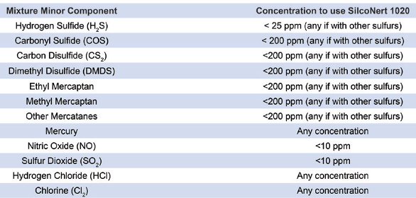
The extreme inertness of SilcoNert 1020 or similar treatments eliminates reactions, and calibration is 10 times faster than when materials are untreated. This reduces calibration gas usage and ensures accuracy. A 0.5-ppm variation in a 5-ppm mixture results in an inaccuracy of 10%. Figure 2 shows the improvement in calibration time using SilcoNert 1020 versus bare stainless steel. Mixtures that can benefit from SilcoNert 1020 are shown in Table 1.
 Figure 2 – The extreme inertness of the SilcoNert 1020 eliminates reactions and hastens calibration times over untreated materials, as shown in comparison with bare stainless steel.
Table 1 – Concentrations of gas mixtures benefiting from the SilcoNert 1020 process
The high concentration of H2S in mixtures used for refinery flare measurement can be thousands of parts per million, which means they are extremely toxic. At such a high concentration, the presence of moisture can cause extreme corrosion effects. Measures must be taken both to protect operators from exposure and the pressure control devices from corrosion. Table 2 compares the corrosion resistance of SilcoNert 1020, Hastelloy C22 and bare 316L stainless steel.
Table 2 – Differences in corrosion resistance among SilcoNert 1020, Hastelloy C22 and bare 316L stainless steel
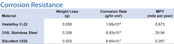
 Figure 3 – A dual-stage 430 SilcoNert 1020 regulator shows an inert gas purge inlet mounted as it would be in a field installation.
The device shown in Figure 3 purges dry nitrogen through the system prior to introducing the high-concentration H2S mixture to reduce corrosion and remove the toxic mixture during cylinder changes, and provides further protection from toxic H2S. Color-coded valve knobs allow the operator to introduce the purge nitrogen; dilute the H2S concentration; and vent the diluted, purged gas to an appropriate location.
Analysis of sulfur content in diesel fuel or liquefied refinery fuel gas must be done when they are in a gaseous state. This requires a special pressure-control device called a vaporizing regulator that is internally heated to convert the incoming stream to a gas without altering the concentration of the minor component, H2S or other sulfurs that may be present. A surface treatment called Dursan (SilcoTek) is used on these units. Figure 4 shows the vaporizing regulator with the LumiShield application, which is even more corrosion resistant and inert, and is resistant to the high temperatures in the vaporizing regulators.
 Figure 4 – The Dursan-treated LumiShield vaporizing regulator is used for liquefied fuel analysis or to counteract the Joule-Thomson effect.
Use of a pressure control that incorporates a heating element is critical when minor components are present that can condense into a liquid phase. This is true when the source is liquid, but is also necessary with high-pressure gaseous fuels like natural gas (which is mostly methane) that are subject to the Joule-Thomson effect, in which the gas rapidly cools as it undergoes a pressure drop. Mixtures are delivered to the instrument at relatively low pressure, normally less than 30 pounds per square inch gauge pressure (psig), or 2 bar. Comparing this to typical cylinder fill pressures at 2000 psig or high-pressure natural gas streams of similar pressure, the regulator delivers such high pressure and the temperature drops across the seat(s) of the device because of the Joule-Thomson effect (which can cause the components to drop into liquid phase and prevent them from reaching the analyzer). Methane, the main constituent in natural gas, is particularly susceptible. Using a vaporizing regulator that is extremely inert may be the only way to accurately deliver a sample and calibration mixture to an analyzer.
In most cases, that is, when not analyzing a liquefied source or a gas susceptible to the Joule-Thomson effect, a dual-stage regulator is effective. With this type of regulator, the pressure falls in stages and temperature drop is reduced.
Dual-stage regulators deliver the standard at a constant delivery pressure, enabling the operator to control both flow and instrument calibration time. This is done by reducing the primary cylinder pressure to an intermediate pressure, that is, the inlet pressure of the second stage of pressure control, which can then be controlled. The benefits of two-stage pressure control outweigh its higher price, allowing users to avoid the cost of repeated manual adjustments and potential inaccuracy of single-stage regulators.
The outlet pressure variation that occurs with only a single stage of pressure control as the inlet pressure drops is typically unacceptable. Even in the best design, the outlet pressure rises 2–4 psig per thousands of psig pressure drop.
Conclusion
The gas pressure regulation system and choice of materials should be compatible with the compounds to which they will be exposed. Precise pressure control is a vital part of this process, and allows operators to control costs and improve accuracy.
Larry Gallagher is specialty gas products manager, CONCOA, 1501 Harpers Rd., Virginia Beach, Va. 23454, U.S.A.; tel.: 800-225-0473; e-mail: [email protected]; www.concoa.com