heology is defined as the study of the flow and deformation of fluids. Based on the need to quickly and accurately set and control processing conditions, optimize product performance, and/or ensure product acceptance, accurate rheological measurements have become essential in the characterization of any flowable materials. By utilizing rheological measurements on new materials, process conditions can easily be determined, and the final product properties and performance can be predicted. Historically, many processes impart high-shear deformation and/or high-shear-rate conditions on a material. Obtaining reliable and accurate data under these conditions has sometimes proven to be problematic and difficult.
Traditionally, capillary rheometers have been used to measure the shear viscosity and elasticity of viscous materials at high shear rates. More recently, extensional viscosity has been obtained through the work of Cogswell et al.1 The interest in high shear rates stems from the mode of deformation a material will undergo in processes like extrusion, film blowing, and injection molding. The design and operational principle of a capillary rheometer are conducive to providing rheological data under these unique processing conditions. The moving piston/die arrangement produces high shear rates on the order of 107 s-1. A measure of elasticity can be determined by measuring expansion of the sample at the die exit, called die swell. Melt fracture can be studied by observing the extrudate.2 Extensional viscosity can be obtained as noted above. As a result, capillary rheometers are widely used in both research environments and quality control laboratories.
Capillary rheometers are versatile and widely used in the rheological measurement of viscous materials where the die sizes normally range from 0.5 to 2.0 mm. However, capillary rheometers suffer from several limitations when attempting to measure fluids with viscosity lower than 1 Pa s: 1) sample flow by gravity through the traditional vertical capillary die when no instrument driving force is applied, and 2) low-pressure readings from the transducer during the measurement. Many times the measured pressure signal can reach the low-end limit of the pressure transducer used.
Another concern is the required length-to-diameter ratio (L/D) of the die for the measurement to be rigorous. According to Macosko,3 an L/D of 60 or higher is required to eliminate the die entrance/exit effects of low-viscosity fluids at high-shear-rate range. This constraint requires that a die with a very small diameter and long length be produced, which is difficult, if not impossible, to fabricate based on normal machining techniques. In addition, other concerns may arise in the measurement of low-viscosity fluids at high shear rates, including viscous heating of the sample during testing, and high-kinetic-energy effects.
A force balance of the translation mechanical system shows that the measured pressure drop ΔP in the capillary die includes the following components: 1) pressure drop due to viscous dissipation (the sample's viscosity) within the capillary Pvisc, 2) pressure needed to obtain the kinetic energy of the testing fluid Pkin, 3) pressure loss due to end effects including the entrance and exit pressure loss Pent and Pexit, and 4) pressure drop for viscoelastic fluids associated with elastic energy Pelastic. The overall measured pressure drop can be written as follows3:
ΔP = Pvisc + Pkin + Pent + Pexit + Pelastic
The kinetic energy pressure contribution for a capillary die is given by:
Pkin = ρν2
where ρ is the density of the fluid, and ν is the average velocity of the flow. The well-known Bagley correction includes both viscous and elastic components and is used to account for the entrance and exit pressure effects of non-Newtonian viscoelastic fluids.
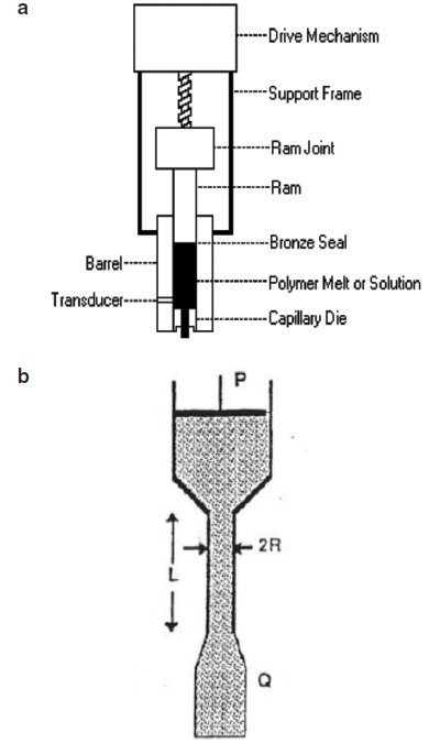
Figure 1 - a) Schematic of complete capillary rheometer, and b) closeup of the die structure with variables.
The basic components of a capillary rheometer consist of a barrel, ram (piston), capillary die fitted inside the barrel, pressure gauge, and force transducer (Figure 1). The material is located within the barrel, and then the ram (or piston) attached with a force transducer pushes the material through the capillary die at a specified rate. Above the die inside the barrel is a pressure transducer, which allows for the measurement of the gauge pressure ΔP within the barrel of the capillary rheometer. The force transducer attached to the ram can be substituted for the pressure transducer and is used as the measured signal ΔP inside the barrel. However, any friction in the system not associated with the sample resistance to flow is also included in the measured output. Using the measured pressure ΔP and known controlled flow rate, one can calculate the viscosity of the test sample. By controlling the velocity of the ram, one can control the shear rate of the sample through the die and calculate the viscosity of the sample at fixed, control shear rates. By varying the components of the capillary rheometer, the range of shear rates and testing condition can be extended to fit the requirement of the experimenter.
Operation of a capillary rheometer is simple but can be more time consuming than a rotational rheometer. This is because the larger sample charge requires more time to reach thermal equilibrium. In addition, it can take significant time for the sample to attain steady-state flow at each shear rate. Further, the operator must assess when the measured stress/force or shear rate reaches steady state for a particular point in the measurement before changing to the next measurement point.
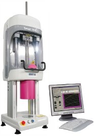
Figure 2 - SmartRHEO capillary rheometer.
This paper describes the SmartRHEO capillary rheometer (REOLOGICA Instruments, Bordentown, NJ) (Figure 2). The data presented demonstrate the instrument's ability to measure not only high-viscosity materials at high shear rates, but also low-viscosity fluids. The ability to test low-viscosity fluids extends the usefulness of the capillary rheometer to a wider range of materials. In addition, the Equilibrium Stress Prediction (ESP) instrument control algorithm permits automatic, operator-free use of the capillary rheometer.
Samples
A commercial, fractional melt index extrusion-grade high-density polyethylene (HDPE) was evaluated at 190 °C to demonstrate the capability of the instrument for testing high-viscosity materials.To demonstrate the instrument’s ability to measure medium-viscosity samples, a polydimethylsiloxane (PDMS) gum was evaluated at 105 °C. Both the HDPE and PDMS were then compared to small amplitude oscillatory shear (SAOS) results obtained with a NOVA rheometer (REOLOGICA Instruments) (Figure 3) at comparable shear rates/frequencies using the Cox-Merz rule.
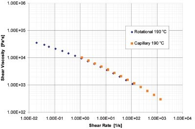
Figure 3 - Viscosity of HDPE at 190 °C using a NOVA rotational rheometer and SmartRHEO capillary rheometer.
A low-viscosity Newtonian oil, along with a modified oil, were evaluated to demonstrate the system's ability to measure low-viscosity fluids at high shear rates. The role of the modifier is to raise the zero shear viscosity while also imparting pseudoplastic, shear-thinning behavior to enhance flowability and providing elasticity, leading to an increase in lubricity at high shear rates.
To demonstrate the utility and accuracy of the ESP algorithm in the SmartRHEO's VisualRheo operational software, both the HDPE and PDMS samples were evaluated using the ESP mode. These automated ESP results were then compared with the traditional manual-testing mode.
Instruments
A SmartRHEO capillary rheometer was used to measure the rheological properties of samples over a wide range of shear rates and test conditions. SmartRHEO is the most technically advanced laboratory capillary rheometer for the determination of the flow behavior of a wide range of materials. The rheometer can measure shear rates from 0.01 to over 10,000,000 s-1, with force capability from 0.1 to 50 kN. A wide variety of die sizes and L/Ds are available. Corrosion-resistant sample chambers, pistons, and dies are also offered. Temperature control is better than ±0.1 °C. Other options include: 1) automatic cleaning, 2) nitrogen blanket, 3) pressure-volume-temperature system, 4) thermal conductivity system, 5) slit die geometry, 6) die swell, 7) stretching unit, and 8) extension viscosity by the Cogswell method. The VisualRheo software can be run in manual, plateau, and automatic ESP mode. The ESP mode is a significant time saver, allowing experiments to be run without user intervention. Other available features in the software are the Weissenberg-Rabinowitsch and Bagley corrections, advanced curve-fitting module, elongational viscosity module, wall slip module, and thermal degradation analysis module. Data exportation to other Windows programs is included as standard.
For the testing of high- and medium-viscosity materials at high shear rates, the SmartRHEO capillary rheometer was utilized with a 1.0-mm die and a die length of 20.0 mm. An L/D of 20 or greater is normally preferred in capillary testing of viscous materials. A standardized procedure was used for all of the capillary testing. First, the instrument was set to the desired test temperature. After the instrument reached the test temperature, the sample was loaded into the barrel of the capillary rheometer and the test was started. The test was set up so that the sample would be at thermal equilibrium for 10 min in the first step of the test. The piston was then lowered until it touched the sample and a maximum load of 0.200 kN was applied. The measuring steps proceeded after the loading and movement of the piston with a controlled velocity and shear rate. Once the steady-state stress at a particular shear rate was reached, a data point was collected, and the next selected shear rate was applied. This step was repeated until all shear rates were completed or the sample began to exhibit flow instability (melt fracture).
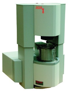
Figure 4 - NOVA rotational rheometer.
HDPE was selected as a high-viscosity sample for its ease of use and well-known rheological behavior in both capillary and rotational measurements. The HDPE was tested at 190 °C, and the viscosity was measured over a shear rate range from 1 to 1000 s-1. At rates greater than 1000 s-1, melt fracture of HDPE occurred, and the experiment was stopped. Results of this measurement are presented in Figure 3. To confirm the capillary data, the HDPE sample was also evaluated on a NOVA rotational rheometer (Figure 4) under SAOS at 190 °C. By applying the Cox-Merz rule, the steady shear viscosity from the capillary rheometer can be directly compared with dynamic shear viscosity from the rotational rheometer. This comparison is also presented in Figure 3. As seen in the figure, the steady shear viscosity of HDPE at 190 °C using the capillary rheometer matched the viscosity measurement from the rotational rheometer. By utilizing both measurement techniques (rotational and capillary), one can accurately measure the viscosity of HDPE from low (0.05 s-1 ) to high shear rates (1000 s-1).