Introduced in the 1980s as an orthogonal
normal-phase method to HPLC, supercritical fluid chromatography (SFC) has demonstrated a number of
benefits to the analytical and preparative
chromatographer. Because SFC
employs green solvents, such as liquid
carbon dioxide, the technique greatly
reduces the use of hazardous and toxic
organic solvents and is gaining more
awareness as an environmentally
friendly alternative to HPLC.1–4
In many applications, SFC demonstrates
additional advantages over conventional
HPLC separations. Because
supercritical fluids possess high diffusivities,
the technique often offers
enhanced separation speed and resolving
power over HPLC—in some applications,
by as much as an order of magnitude.
Additionally, SFC systems can
reequilibrate faster than HPLC systems
and therefore can be ready to process
other samples in a shorter time frame.
Despite these inherent advantages, SFC has yet to gain widespread acceptance
as the separation method of
choice, particularly in chemical and
pharmaceutical laboratories, where
large numbers of high-purity compounds
are desired. While HPLC provides
a convenient mechanism to isolate
and collect sample fractions in an
efficient, though costly manner, SFC
systems have been limited by their
restrictive fraction collection capability.
SFC fraction collectors are typically
expensive and bulky, requiring
valuable space inside a fumehood, and
are capable of collecting only a limited
number of fractions per separation.
Furthermore, SFC fraction collectors
do not operate at atmospheric pressure,
making the hardware requirements
and collection mechanism
more complex.
The fraction collector described in this
article is designed specifically for SFC, delivering HPLC-like convenience to
SFC isolation and purification. Based
on novel centrifugal technology, the
CFC-2 fraction collector (Modular
SFC, North Attleboro, MA) overcomes
the complexities and limitations of conventional SFC fraction
collection and allows chromatographers
to migrate existing HPLC methods
and develop new achiral applications
to take advantage of the benefits
of SFC chemistries.
SFC fraction collection with HPLC-like convenience
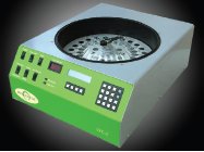
Figure 1 - The CFC-2 fraction collector enables collection of up to 24 fractions while operating at atmospheric pressure, eliminating the need for pressurized equipment and complex methodology required for conventional SFC fraction collectors. The fraction collector can be connected to any SFC system.
The CFC-2 fraction collector (Figure
1) is capable of collecting up to 24
samples (27 mL of modifier solvent
per fraction) in the same 20 mm ×
150 mm glass tubes used in a conventional HPLC fraction collector. The
instrument employs patent-pending
centrifugal technology that captures
nonvolatile materials entrained in
the eluent stream from any SFC system
with better than 90% recovery.
Fractions are collected at atmospheric
pressure, eliminating the complexity
and pressurized vessel requirements of
typical SFC fraction collectors. The compact instrument (20 in. wide × 9
in. high × 26 in. deep) can be placed
on a laboratory bench, outside of a
hood, because all vapors are directed
through an exhaust hose to the nearest
laboratory vent system.
Novel centrifugal
technology
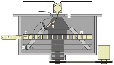
Figure 2 - CFC-2 fraction collector enclosure (1) operates at atmospheric pressure and prevents volatile vapors from escaping. A rotor (2), with a capacity of 24 fraction collection tubes, spins at 1500 rpm. A flexible eluent tube (3) directs the flow from the SFC system into each fraction collection tube while the rotor is spinning. Liquids and solids are trapped in the bottom of the collection containers (4) due to the centrifugal force created by the rotor. Volatile gases are expelled from the collection tube and blown by fan blades in the rotor (5) out a flexible exhaust hose (6). The hose is connected to the laboratory venting system, eliminating the need to place the system beneath a fumehood.
The fraction collector uses centrifugal
force to perform a density separation
(effectively separating the gas
phase from liquids and solids) upon
the spray from the eluent tube. The
technology incorporates a rotor, containing up to 24 fraction collection
tubes, that spins at 1500 rpm (concentrator
speed). The sample collection
tubes are standard, off-the-shelf
glass containers, which eliminate the
need to use pressurized steel collection
containers or a pressurized cassette having glass collection containers
required by typical SFC fraction collectors (Figure 2).
A diverter valve directs the eluent
flow from the backpressure regulator
of the SFC instrument to either
a waste container or to the eluent
dispensing tube entering the fraction
collector. To prevent cross-
contamination
among collection
tubes in the rotor, the custom valve
has the ability to stop the eluent flow
for the quarter second that the distributor
mechanism is advancing the
eluent tube between containers while
the rotor continues to spin. This
momentary stop flow condition is
possible because most of the volume
in the tubing to the SFC instrument
is compressible CO2 gas.
The flexible eluent tube fixed to the
valve’s collect outlet directs the flow
from the SFC system into one sample collection container while the
rotor is spinning. The eluent tube
extends into the fraction vessel
and dispenses eluent having volatile
and nonvolatile compounds,
even solid precipitates that form
as the nonpolar
CO2 becomes gaseous
and the remaining organic
modifier becomes too polar to
keep the sample solubilized.
As the eluent spray contacts the
wall of the spinning container, the
centrifugal force causes the highest-density
components (liquids and solids)
to accumulate in the bottom of
the collection container. The CO2
gas, being the least dense part of the
eluent, spills out of the fraction container
opening into the rotor housing.
Centrifugal fan blades between
the rotor disks blow volatile vapors
through an exhaust hose to the nearest
laboratory vent facility, eliminating
the need to locate the fraction
collector inside of a fumehood.
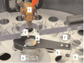
Figure 3 - Eluent distribution system: 1) diverter valve for “waste,” “collect,” and “stop flow” (while switching fractions); 2) fixed end of flexible eluent tube connected to “collect” outlet of valve; 3) indexing
mechanism for redirection of eluent tube during fraction change; 4) mechanism to withdraw eluent tube from containers during fraction change; 5) PTFE guide channel supports and directs rotating eluent tube; 6) rotating end of eluent tube inserted into collection container; and 7) one of 24 collection containers in fraction collector rotor.
To maximize nonvolatile compound
yield, the eluent tube is inserted some
distance into each fraction container
during collection. When the distributor
mechanism executes a “next fraction”
command, a retraction mechanism
withdraws the eluent tube from the current
container before advancing to the
next container. After the new container
is reached, the eluent tube is extended
into the container before the diverter
valve resumes the eluent flow (Figure 3).
Because the rotor spins the fraction
containers to generate the required centrifugal
force to capture the nonvolatile
components from the eluent, collection
of consecutive fractions into adjacent
fraction tubes would eventually imbalance
the rotor. To maintain equal weight
distribution during the collection process,
the instrument is designed to collect
consecutive fractions in containers
that are 165° apart from each other on
approximately opposite sides of the rotor.
“Waste/collect” and “next fraction”
controls are enabled by contact closure
outputs on the SFC instrument.
The CFC-2 system is also internally
programmable to operate these functions
by time or by detecting peak
height thresholds generated by an
analog output from the SFC system’s
detector. A chart mark contact closure
is available to document when transitions
are made between collection
containers. Future versions will allow
mass-directed fractionation capability.