In recent years, interest has been growing in performing differential scanning calorimetry (DSC) at higher temperature-scanning rates.1 A variety of material characterization challenges exist that can benefit dramatically from rapid heating or cooling rate experiments. Primarily, the investigation of metastable states and time-dependent transitions in polymers and pharmaceutical materials has fueled the interest. Other potential applications include experiments that more closely model actual material processing conditions, for example, high cooling rates that occur in molding of polymeric materials. Higher scanning rates will also increase the heat flow sensitivity for subtle transitions, although this benefit is usually tempered by the small mass requirement of the rapid-scanning instrument.
Currently, rapid-scanning experiments are performed using either a conventional DSC2 modified to increase the heating and cooling rates or so-called chip calorimeters,3–5 where the calorimeters are fabricated using semiconductor processes. Each method has its inherent advantages. The heating and cooling rates achievable by conventional DSC instruments are rather modest, being on the order of a few hundred K/min over a limited temperature range. These experiments are further limited by the relatively long measurement time constant of the conventional DSC transducer (2–3 sec), which diminishes the instrument’s ability to resolve closely spaced transitions. However, sample preparation and handling are simple and familiar to all DSC users, while precise weighing of the sample facilitates quantitative measurements of heat capacity and enthalpy.
Alternatively, chip calorimeters offer heating and cooling rates as high as 106 K/sec or more with measurement time constants on the order of 10–3 sec or less. These devices are extremely small and require that the sample be applied directly to the calorimeter using spin coating or other similar techniques. As such, sample handling and preparation are much more difficult, and it is not possible to directly weigh the sample, complicating quantitative measurement of specific enthalpy and specific heat capacity. Finally, because the membranes that support the calorimetric elements are extremely thin, chip calorimeters are very fragile. While they may be cleaned and reused, chip calorimeters are often good for only a single experiment, severely limiting the practicality of the experiment.
Experimental
A DSC has been designed specifically for operation at high scanning rates—up to 2000 K/min in heating with similarly high cooling rates. Known as Project RHC (TA Instruments, New Castle, DE), the rapid-scanning DSC has been designed to retain the ease of use and sample preparation of conventional DSC. Reduction of the masses of the sample, sample containers, sensor, and DSC enclosure are necessary prerequisites in the design of a rapid-scanning DSC. Sample pans are 1.6 mm in diam, weighing less than 2.0 mg for use with samples 1.0 mg or less. The total mass of the measuring cell, including the sensor, sample pans, and the silver enclosure, is less than 25 g.
Key technologies introduced by the manufacturer are essential to its performance and are incorporated into Project RHC. Tzero® technology6 improves the resolution and sensitivity of the measured sample heat flow rates, especially for very weak effects, and improves the instrument baseline. Infrared heating, introduced in the Q5000IR TGA7 (TA Instruments), provides a “massless” infrared heat source. By replacing slow-responding, high-mass, large thermal resistance, conventional heating elements with the nearly instantaneous response of quartz halogen lamps, Project RHC provides the very rapid response that is essential to achieving the desired heating and cooling rates.
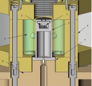
Figure 1 - Cross-section through the rapid-scanning DSC.
Figure 1 shows a partial cross-section through the DSC assembly of the instrument, including the DSC sensor and enclosure, infrared heating system, heat sink, and thermal resistance between the DSC enclosure and the heat sink. The sensor assembly comprises sample (1) and reference holders (2) 1.65 mm in diam by 1.65 mm deep into which the sample and reference pans are placed. As described in Ref. 6, two temperature differences, ΔT and ΔT, are measured along with Ts and Tr, the sample and reference holder temperatures, and T, the temperature at the base of the sensor that is used for temperature control. The sensor assembly is contained within a high-purity silver enclosure (3); a high-emissivity coating applied to its external surfaces ensures efficient heating by the four quartz-halogen lamps (4) surrounding the DSC. The lamps and the DSC assembly are further enclosed by a gold-plated multielliptical reflector (5) that concentrates the radiant energy emitted by the lamps on the exterior of the DSC enclosure, thereby heating it. The DSC enclosure is cooled by a liquid nitrogen-cooled heat sink (6) via a thermal resistor (7) interposed between the enclosure and the heat sink. The thermal resistor comprises a narrow gap through which gases of different thermal conductivity are purged, varying the cooling power applied to the DSC. High-conductivity gases such as helium may be used to maximize cooling rates, while lower-conductivity gases such as nitrogen may be used to facilitate maximum heating rates. The reflector assembly is also cooled by the heat sink.
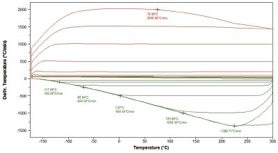
Figure 2 - Heating and cooling rates envelope of the Project RHC rapid-scanning DSC.
Figure 2 shows the range of heating rates available with Project RHC. Linear scanning rates up to 1500 K/min in heating and 1000 K/min in cooling are easily achieved over the broad temperature range typical for the proposed applications. Ballistic heating and cooling permit even higher instantaneous rates.
Applications
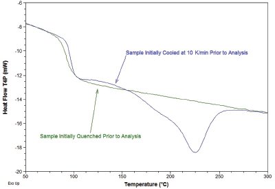
Figure 3 - Analysis (500 K/min) of a polyester sample with differing thermal histories.
The desire to heat and cool at rates much faster than traditional DSC instruments is mainly application-driven. For example, many time-dependent transitions can be suppressed at high heating rates that allow the investigation of metastable states in materials. In the case of thermoplastic polymers, the cold crystallization peak often encountered when heating a semicrystalline or amorphous polymer can complicate the analysis of the metastable structure and the determination of initial crystallinity. Figure 3 shows a comparison of a quenched 100% amorphous and a semicrystalline polyester sample (initially cooled at 10 K/min), both heated at 500 K/min. Scanning at this rate effectively eliminates crystallization during heating usually seen in quenched samples, and provides a true indication of the initial morphology of each sample.
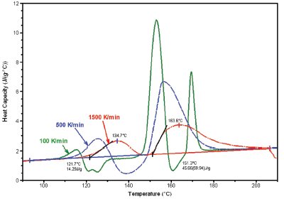
Figure 4 - Analysis of a pharmaceutical polymorphic transition at a variety of heating rates (shown).
Analogous applications exist in pharmaceutical science,8–13 particularly in the study of polymorphism. The ability to suppress polymorphic transitions in pharmaceutical compounds is critical to understanding their morphology and structure. Figure 4 shows the analysis of a pharmaceutical sample that exhibits polymorphic transformation at heating rates up to 500 K/min. This transformation is effectively suppressed by scanning at 1500 K/min, a rate easily achievable in the Project RHC instrument.
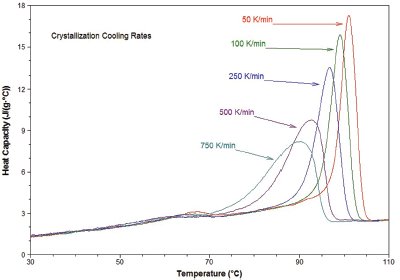
Figure 5 - Crystallization of low-density polyethylene at a variety of cooling rates (shown).
A second area of application lies in simulation of process conditions, particularly the rapid crystallization of polymeric samples. During processing, polymers are often subject to cooling rates in excess of 1000 K/min. However, traditional DSC instruments are not capable of achieving comparable ballistic cooling rates. The data in Figure 5 show crystallization from the melt of low-density polyethylene at a variety of constant cooling rates up to 750 K/min. The ability to achieve these rates will provide the polymer scientist with a new tool in the study of crystallization kinetics. In addition, the ultrafast ballistic cooling capability of Project RHC simplifies isothermal crystallization experiments as well.
A final application is in the area of modulated-temperature DSC (MTDSC). The traditional limitation on underlying heating rate for these experiments is due to long signal-time constants (1–5 sec). The time constant of the Project RHC design is about 0.1 sec, which should allow for a 10× increase in the underlying heating rate of the MT-DSC experiment, without significant loss of resolution.
Summary
The rapid-scanning DSC described in this article allows substantially higher scanning rates on manageable sample sizes that provide quantitative heat flow results. The potential applications for the instrument are broad, and further investigation of this burgeoning technique will be facilitated with Project RHC.
References
- Wunderlich, B. Fast and Super-Fast DTA and Calorimetry; Proceedings of the 32nd NATAS Conference, Oct 4–6, 2004, Williamsburg, VA; Rich, M.J., Ed. CD edition, 2004; p 32.
- a) Pijpers, T.F.J.; Mathot, V.B.F.; Goderis, B.; van der Vegt, E. High Performance DSC—High Scanning Rate DSC: Application to Polymers; Proceedings of the 28th NATAS Conference, Oct 4–6, 2000, Orlando, FL; pp 32–7. b) Pijpers, F.J.; Mathot, V.B.F.; Goderis, B.; Scherrenberg, R.L.; van der Vegte, E.W. Macromolecules 2002, 35, 3601–13.
- Denlinger, D.W.; Abarra, E.N.; Allen, K.; Rooney, P.W.; Messer, M.T.; Watson, S.K.; Hellman, F. Rev. Sci. Instrum. Apr 1994, 65(5), 946–59.
- Efremov, M.Y.; Olson, E.A.; Zhang, M.; Lai, S.L.; Scheittekatte, F.; Zhang, Z.S.; Allen, L.H. Thermochim. Acta 2004, 412, 13–23.
- Minakov, A.A.; Schick, C. Rev. Sci. Instrum. 2007, 78, 073902 (and references therein).
- Danley, R.L. Thermochim. Acta2003, 395, 201–8.
- Dallas, G. Am. Lab. 2006, 36(1), 22.
- Saunders, M.; Podluii, K.; Shergill, S.; Buckton, G.; Royall, P. Int. J. Pharm. 2004, 274, 35–40.
- Gabbott, P.; Clarke, P.; Mann, T.; Royall, P.; Shergill, S. Am. Lab. 2003, 35(16), 17.
- McGregora, C.; Saunders, M.H.; Buckton, G.; Saklatvalaa, R.D. Thermochim. Acta2004, 417(2), 231–7.
- Gramaglia, D.; Conway, B.R.; Kett, V.L.; Malcolm, R.K.; Batchelor, K. Int. J. Pharm.2005, 301(1–2), 1–5.
- Hurtta, M.; Pitkänen, I. Thermochim. Acta2004, 419(1–2), 19–29.
- Buckton, G.; Adeniyi, A.A.; Saunders, M.; Ambarkhane, A. Int. J. Pharm.2006, 312(1–2), 61–5.
Mr. Danley is Research Manager, Mr. Caulfield is Senior Product Marketing Specialist, and Dr. Aubuchon is Thermal Analysis Product Manager, TA Instruments, 109 Lukens Dr., New Castle, DE 19720, U.S.A.; tel.: 302-427-4000; fax: 302-427-4001; e-mail: [email protected].