Total sulfur and nitrogen (TS/TN) levels are commonly used parameters in the petrochemical, natural gas, and oil refining industries, and the need for their determination is growing due to the increasing environmental and process requirements. Total sulfur content is of great importance for process and quality control (QC) of specifications in finished products commonly used in the petrochemical industry. Sulfur components in process feeds are capable of damaging the catalyst performance in the refinery processes, lowering the refinery efficiency, and consequently lowering the profitability. The total sulfur content in automotive fuels is closely monitored in order to comply with international regulations. The American Society for Testing and Materials (ASTM) published the ASTM D5453 method specifically for the petroleum industry for the determination of total sulfur content in liquid petroleum products by UV-fluorescence (UV-F). This method is applicable for liquid hydrocarbons with a boiling point between 25 and 400 °C, including naphtha, distillates, ethanol, gasoline, and diesel/biodiesel blends with sulfur content in the range of 1–10,000 mg/kg (ppm).
The TITAN 4000 total sulfur analyzer (Thermo Fisher Scientific, Delft, The Netherlands) has been developed for the determination of total sulfur specifically for this range of elements. Due to its patent-pending injection port and folded turbo combustion tube, the analyzer can inject liquid samples within any boiling point range. This article describes the use of the TITAN 4000 for the determination of total sulfur content in liquid petroleum in accordance with the ASTM D5453 method.
Designed with a dedicated gas connector to establish multiple gas paths between the analyzer modules without the use of any tubing and glass connectors, the total sulfur analyzer is compact, with optimal connectivity capabilities between the individual modules. It consists of an aluminum block with small channels, connecting manifolds of adjacent analyzer modules. The surface is anodized and treated with a PTFE coating. Because of its modular design, it is possible to switch between modules easily, limiting the need to troubleshoot and repair a module on-site. Furthermore, it allows the user to add a detector module to the system at a later stage.
Injection system
Traditionally, designs of liquid injection devices are based on full evaporation of the injected sample. In this case, the temperature of the quartz glass injection port and the needle has to be maintained at 400 °C at least. The sample is not allowed to combust in this part of the injector; therefore, argon is required as inert carrier gas. The problem with this injection technique is that all of the sample must be evaporated at 400 °C and must not crack at that temperature. The high temperature of the needle could result in deposition of cracking products within the needle, causing it to block, even though measures were taken to create a laminar flow.
Another option is the direct injection of the sample in the combustion tube; however, this results in droplets of sample that combust vigorously in the oxygen atmosphere. This creates local hot spots, resulting in undesirable combustion products. Moreover, the carbon dioxide (CO2) produced forms a blanket around the droplets, leading to a local oxygen deficiency, which promotes soot formation.
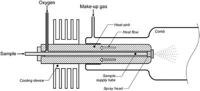
Figure 1 - Simplified layout of the spray injector.
Based on nebulizing the sample with a gas flow, the injection device technology described here (Thermo Fisher Scientific) eliminates the need for an inert carrier gas. It was designed for complete sample introduction into the inner combustion tube and optimal mixing with oxygen. In addition, keeping the needle and the injector at the lowest possible temperature covers an extensive range of liquid applications, regardless of their final boiling point. This also means that very heavy products can be injected as long as they can be dissolved in a solvent (see Figure 1).
Combustion tube
Traditional combustion tubes are oriented horizontally with inlet and outlet on opposite sides. This allows injection and detection to be located at each side of the analyzer, resulting in an elongated system, using much greater laboratory space.
The turbo combustion tube used in this type of total sulfur analyzer offers less efficient mixing of carrier gas, oxygen, and sample, which results in limited control of the combustion and longer evacuation time inside the combustion tube. The gas velocity is not high enough to create enough turbulence. Due to the horizontal orientation of the combustion tube, the carrier gas/oxygen mixture segregates from the combustion gases, which sink toward the bottom of the tube.
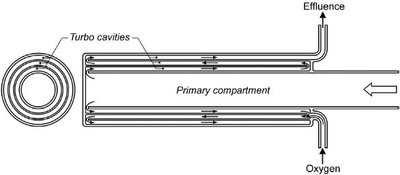
Figure 2 - Simplified cross-section of the folded turbo tube.
The patent-pending combustion tube for the TITAN 4000 follows the high-level laminar plug flow principle. The folded turbo tube is divided into a primary compartment and a turbo compartment that is folded back (hence the name) over the outside of the primary compartment, and includes a number of separate tube-shaped cavities (Figure 2).
The mixing performance of the folded turbo tube is highly improved by employing up to nine static mixers in the cavities of the turbo compartment. One of the issues with quartz combustion tubes at high temperature is that alkaline metals in the combustion product will settle on the surface of the tube. Locally, this will cause an area with a lowered melting point. Particularly when the tube is cooled down, these areas will form separate crystals, causing the material to become brittle. In previous designs, tubes affected by this deterioration had to be replaced completely. In the newly designed combustion tube, the first part of the tube is separated from the folded turbo tube. Only replacement of the inner tube is necessary, making the system more cost effective.
By directing gas flows in both vertical directions, both the inlet and the outlet of the tube can be located at one end. The bottom part of the tube remains closed, and both injection and outlet to the detectors are located on the top side of the tube, benefiting from the compact design.
Gas conditioning module
The gas conditioning module contains a number of mass flow controllers and pressure control and regulation devices. The pressures of supplied argon and oxygen are controlled by two regulators inside the unit. This allows greater flexibility regarding the pressures of the offered gas supply. The inlet pressures are measured, and below a set value of 2 bar the system will not allow sample injections. In previous analyzers, the gas flow through the detector was pulled by the vacuum pump and regulated by a capillary. Make-up gas flow was pulled from an open connection on the back of the instrument.
The TITAN 4000 ensures that this makeup gas flow is provided by the oxygen supply and regulated by the pressure control valve (PCV). This valve is able to quickly react to pressure drops or rises, adding or reducing an additional oxygen flow. This make-up gas flow runs through the flow exchange module (FEM), where the flow is measured. The flow readout and the reaction of the PCV are accurate enough to observe the formation of combustion gases and removal of water by the permapure dryers.
TS detector module
The TS detector module, containing the pulsed-UV-F detector, is connected through another gas connector set. This module contains a pulsed UV lamp for the excitation of SO2 to SO2* and a photomultiplier tube (PMT), which detects the light emitted by SO2* returning to its ground state. The automatic gain control (AGC) ensures a constant energy level of the UV lamp for very good long-term stability and reduces the need for calibration. The ease of connectivity to the TS-UVF module can be extended with a dedicated TN-CLD (chemiluminescence detecor) for simultaneous TN/TS determination, or exchanged for a combined TN/TS module to save bench space.
Principle of operation
The TITAN 4000 incorporates an automatic syringe-driven liquid introduction device, combustion oven, gas conditioning, and sulfur detection module system to comply with ASTM D5453. The liquid sample is sprayed into the high-temperature, dual-zone combustion oven fitted with a quartz combustion tube. The patent-pending injection port and combustion tube require only oxygen and ensure a complete oxidation of the sample into mainly CO2 and water in an oxygen-rich environment. The sulfur components are oxidized into SO2. Any water and interferences are removed by the conditioning stage, which involves a permeable membrane dryer tube. The dried and clean gas with SO2 is led to the TS-UV-F detector module for the determination of the total sulfur content in the sample.
Analysis
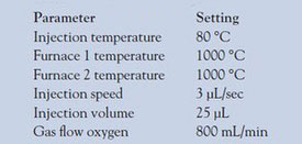
Table 1 - System settings
The total sulfur analyzer is calibrated with two sets of calibration standards, which are based on dibutyl sulfide in isooctane, as suggested in the ASTM D5453 method. Each standard has been analyzed four times to check the repeatability of the analyzer.
Table 1 shows system settings selected to run the calibration lines and test the QC and practical samples on total sulfur determination.
Table 2 - Set of standards used for calibration lines
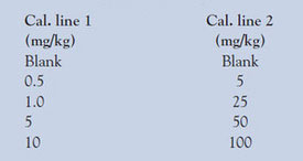
After the calibration curves were run, an ultralow-sulfur diesel (ULSD) QC sample was analyzed nine times to show the repeatability of the TITAN 4000 analyzer, and a set of hydrocarbon samples were run to show that the application coverage complied with ASTM D5453 regulations. The standards used for the calibration are shown in Table 2.
Results
Figures 3 and 4 show the two individual calibration curves obtained from the total sulfur analyzer and demonstrate the linearity of the system.
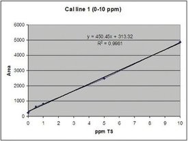
Figure 3 - Cal. line 1: blank, 0.5, 1.0, 5, and 10 mg S/L.
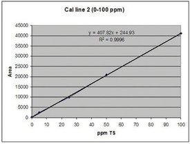
Figure 4 - Cal. line 2: blank, 5, 25, 50, and 100 mg S/L.
Table 3 - Test data: Total sulfur determination in QC ULSD sample
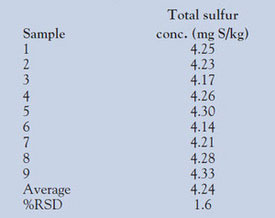
Table 4 - Test data: Total sulfur determination
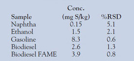
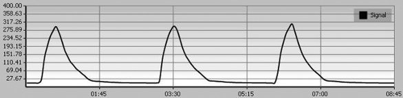
Figure 5 - Sample peaks of 10 ppm TS.
A QC ULSD sample was analyzed nine times using the TITAN 4000 with an injection volume of 25 μL. The results obtained are shown in Table 3.
After the ULSD sample was analyzed, a set of general petroleum products was analyzed for total sulfur content using the TITAN 4000 model and measured in triplicate. The results obtained are shown in Table 4.
The injection and combustion technology within the TITAN 4000 decreases analysis times for an individual sample to less than 3 min. Figure 5 shows the triplicate measurement of a 10-ppm sulfur sample and illustrates this short analysis time of 3 min per sample injection. This means that within 9 min the user achieves a triplicate fully automated process, resulting in optimal repeatability.
Summary
The use of innovative injection and combustion technologies on the TITAN 4000 has created a compact, fast, and reliable trace-level sulfur analyzer. Alignment of the individual modules is accurate due to the instrument’s gas connection design, and productivity is significantly enhanced with the use of a 105-position autosampler, ensuring high performance. The availability of a number of gas flow and pressure sensors results in an easy-to-use diagnostic analyzer with remote-access capabilities for maximum uptime. The results obtained during the total sulfur determination application show that the TITAN 4000 is able to detect total sulfur within 2 min, allowing good repeatability for the ULSD sample, and covers an application scope for general petroleum-related products while complying with ASTM D5453 requirements.
Mr. van der Windt is Product Manager, and Mr. van Strien is Product Marketing Manager, Thermo Fisher Scientific, Voltaweg 22, 2627 BC Delft, The Netherlands; tel.: +31 (0) 15 257 1314; fax: +31 (0) 15 257 2297; e-mail: [email protected].