Recent high-sensitivity and high-throughput trends in liquid chromatography, influenced largely by the latest interfacing technologies of mass spectrometry, seem to demand further improvements in sample introduction technology. It may be preferable to minimize any source of extracolumn band broadening when using short, small-particle columns showing extremely small retention volumes for analytes.
Commercially available LC autosamplers can be roughly divided into two groups. In the most widely used instruments, the sampling needle becomes part of a high-pressure flow system once a chromatographic run begins with a valve position change. The sampling needle in more traditional systems always operates under atmospheric pressure.1 The former systems require less time for sample introduction and generally demonstrate fewer memory effects in high-sensitivity analyses. Memory effects grew in importance as the dynamic range of LC improved.2–4 The latter type of autosampler is sometimes preferred because it is easy to build a system with high-pressure resistance (e.g., more than 80 MPa).
In both types of autosampler, a plug of collected sample solution is transferred through a flow-changing device, such as a rotary valve, and several tubing connections, into a separation column. There are, inherently, contacts between the sample solution and the inner surfaces of the flow path. Some parts of the surfaces are often difficult to self-clean in the process of chromatographic runs, and thus cause a memory effect, or carryover. In addition, the valve and tubing connections, which are located upstream of the separation column, are known to contribute to a large extent to band broadening in the separation.
An autosampler was designed that transfers a collected liquid sample directly to a column without passing it through any flow-changing device or tubing connection. In addition to a six-way valve used in conventional systems, a new direct injection valve (DIV) was designed and used in the autosampler. The structure and performance of the autosampler are discussed in this paper.
Experimental
DIV installation
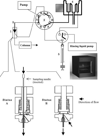
Figure 1 - Schematic diagram of the total flow system and direct injection valve. Sample is injected and the chromatographic run begins at Status A. Sample collection with the needle and needle cleaning take place during Status B. 1) DIV, 2) switch valve, 3) needle, 4) ultrasonic cleaning port, and 5) syringe. (Reproduced from Ref. 6.)
The autosampler model used as the basis of this study was a 3133 HTS Autosampler Z (Shiseido, Tokyo, Japan) equipped with an ultrasonic cleaning device. Its structure is described in detail in Ref. 5. A DIV produced by Shiseido Irica Technology (SIT, Kyoto, Japan) was installed onto the autosampler (Figure 1). An additional electronic circuit was attached to synchronize the two positions (A and B) of the DIV and the switching valve, so that the two mechanical units operated simultaneously. The tubing connections were altered slightly from those in the commercial model to those shown in Figure 1.
The DIV has a long hole that guides a sampling needle to the end of the tubing, leading directly to a separation column. In Status A, the needle is inserted into the DIV and pressed against the end of the tubing. In the transition to Status B, the needle is pulled out of the DIV first, and then the upper part of the DIV rotates to close the hole. The hole guiding the needle is located off-center so that the rotation of the top part can close it.
In Status A, the mobile phase flow carries the sample from the needle to the column, and chromatographic separation begins. In Status B, the needle goes to a vial position, collects the sample, cleans its outer surface at the ultrasonic cleaning port, and moves back to the DIV valve, while the mobile phase flows from the pump to the column through the closed DIV.
Evaluation of separation efficiency and carryover
Chromatograms obtained with the original 3133 HTS autosampler and with its modified version with a DIV were compared, as discussed below. Four standard reagents (uracil, methyl benzoate, toluene, and naphthalene), chlorhexidine, and all the other reagents to prepare a mobile phase were obtained from Sigma- Aldrich Japan (Tokyo).
To evaluate the separation efficiency, the standard mixture (containing 100 ppm each) was run under the following conditions—column: CAPCELL PAK C18 IF 1.8 µm, 2.0 mm i.d. × 50 mm (Shiseido); mobile phase: 70% acetonitrile; flow rate: 200 µL/min; temperature: 25 °C: detection: 254 nm. An HPLC system was constructed using components of the NANOSPACE series (Shiseido), consisting of a model 3133 HTS autosampler (or its modified version, as described earlier), 3004 column oven, 3001 inert pumps, and 3017 UV6000LP diode array detector. EZChrom Elite for Shiseido (Shiseido) was used as an instrument controller and data system.
Evaluation of carryover was carried out with standard chlorhexidine solutions (0, 12, and 1200 ppm) under the following conditions—column: CAPCELL PAK C18 IF 1.8 µm, 2.0 mm i.d. × 50 mm; gradient elution A: 100 mM NaClO4, 10 mM NH4H2PO4 (pH 2.6), B: acetonitrile, 30%B (0 min)–70%B (3 min)–30%B (3.1–5 min); total flow rate: 200 µL/min; temperature: 25 °C; detection: 254 nm. The instrument system was the same as that described above. The sequence of sample runs was as follows. First, the 12-ppm solution was run to calibrate the system. Then, the 1200-ppm solution was run, which was supposed to show a huge signal saturating the detection scale. Finally, 0-ppm (blank) solution was run to see if any carryover was observed.
Results and discussion
The square of variance of a chromatographic peak can be expressed as a sum of those contributing at each process.7
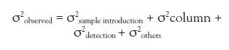
Most of the observed peak variance is generated at a separation column in a conventional application with 4.6-mm i.d. columns at 1.0 mL/min. Chromatographers rarely discuss the effect of instrumentation on evaluating commercially available 4.6-mm-i.d. columns. When an LC run time is reduced to less than a few minutes in some applications of the current high-throughput systems with the use of a short and narrow sub-2-µm column, the retention volume of an analyte is often reduced to less than 1 mL. Band broadening at sample introduction seems to be highly significant for a peak having a small retention volume. One of the objectives of the study was to determine to what extent the modified autosampler can reduce band broadening in such cases.
Another issue is the carryover generated with the autosampler. Carryover is becoming a serious problem, particularly in the fields of pharmacokinetics and clinical analysis, where concentrations of unknown samples often vary widely. The authors have reported on several autosamplers that reduce carryover, including one equipped with an ultrasonic cleaning device.6 While carryover can largely be reduced by applying several methods to clean a needle for sample collection in the case of isocratic elution, reducing carryover in a gradient elution is not easy. Not only does substance remain on the needle, but that left at certain locations, such as a rotary valve, contribute to the same peak area after being focused at the top of the column.
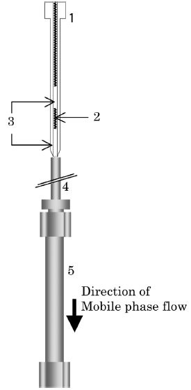
Figure 2 - Schematic diagram of sample introduction. 1) Sampling needle, 2) sample liquid, 3) air, 4) tubing, and 5) separation column.
The structure of the autosampler shown in Figure 1 was intended to minimize the band broadening and carryover generated at sample introduction. A liquid sample collected by the needle at the atmospheric pressure is transferred to the separation column without passing through any flow-switching device. The connection between the needle and the column during chromatographic runs is illustrated in Figure 2. The sequence of air–sample–air in the needle is identical to that used in the commercial model to which the autosampler is compared. The structure was designed to minimize system volume between the sample and the column, and remove any surface that is not self-cleaned by the mobile phase flow, and becomes a potential source of carryover.
Separation efficiency was compared between two autosamplers—model 3133 and its modified version equipped with a DIV. The simplification of sample transfer resulted in a slight reduction in retention times for all of the standard compounds. As intended, resolution between the peaks was clearly improved (Figure 3). The baseline separation between the second and third peaks (methyl benzoate and toluene) was easy to recognize.
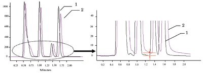
Figure 3 - Comparison in resolution of standard compounds. 1) Modified autosampler and 2) model 3133.
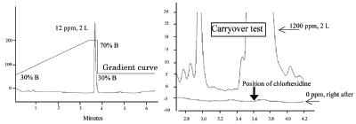
Figure 4 - Carryover test with chlorhexidine based on the gradient elution.
Evaluation of anticarryover performance was attempted with chlorhexidine, a compound known to show carryover because of its strong basicity and hydrophobicity. The test was based on gradient elution. As described earlier in the text, it had been difficult to eliminate a memory effect in a gradient elution, although a large portion of fast LC-MS applications performed today are based on gradient conditions. The autosampler equipped with a DIV successfully eliminated carryover in the test (Figure 4). The absence of an uncleanable surface along the pathway of the plug of sample liquid seemed to contribute to the results. The conventional model showed a 3-mV high carryover peak, corresponding to 0.015% of the previously introduced amount, in the same test (data not shown).
The “straight-to-column” structure shown in this paper requires a DIV in addition to other units used in conventional systems. While the initial results showed the method to be successful, other applications need to be studied. Practically speaking, the design may lead to a significant increase in cost when commercialized. However, it is still important to explore ways to improve sample introduction in order to best utilize new column and detection technologies.
References
- Krstulovic, A.M.; Brown, P.R. Reversed-Phase High Performance Liquid Chromatography; John Wiley & Sons, New York, NY, 1982, p 48.
- Dolan, J.W. LC·GC2001, 19(2), 164.
- Dolan, J.W. LC·GC2001, 19(3), 290.
- Dolan, J.W. LC·GC2001, 19(10), 1050.
- Togashi, Y.; Mibayashi, K.; Mita, M.; Kaneko, T.; Shirota, O. Am. Lab.2004, 36(14), 33-7.
- Hirayama, A.; Shirota, O. Japanese patent application, to be laid open in 2010.
- Krstulovic, A.M.; Brown, P.R. Reversed-Phase High Performance Liquid Chromatography; John Wiley & Sons, New York, NY, 1982, p 23.
The authors are with the Shiseido Research Center, 2-2-1 Hayabuchi, Tsuzuki-ku, Yokohama 224-8558, Japan; tel.: +81 45 590 6236; fax: +81 45 590 6088; e-mail: [email protected].