Terahertz sensing and imaging technology has been investigated in various fields, including security, medicine, biochemical applications, and art.1-4 One of the most powerful tools for terahertz imaging is terahertz-time domain spectroscopy (THz-TDS), with transmission-type THz-TDS widely used for measuring the dielectric response of various materials such as semiconductors, dielectrics, and biological tissues. Two-dimensional terahertz transmission images are easily obtained by transversely scanning such samples. Furthermore, the spectroscopic imaging capabilities of THz-TDS have recently been demonstrated. Opaque samples having either a high water content or metal backing can be measured with reflection-type THz-TDS, which can be used not only for spectroscopy but also for tomographic imaging.5,6
Since the electromagnetic field of the subpicosecond terahertz pulses is measured directly with THz-TDS, the multilayered structure of a sample can be imaged by detecting the echo pulses reflected from each layer. This technique is valuable in industry because the unique transmission characteristics of terahertz waves enable the inspection of multilayered paints in industrial products or tablet coatings,7,8 which are not measurable with optical coherence tomography (OCT) based on an optical light source.9
As restricted by the temporal duration of the terahertz pulses used, the conventional axial resolution of terahertz tomography remains a few tens of microns, although an attempt to improve the axial resolution of time-of-flight measurements has been reported.10 In the technique described here, a terahertz interferometer was added to the reflection-type THz-TDS configuration to attain a resolution of 12.5 µm. Although this method has proven effective as a profilometer, it has not been investigated as a tomography system whereby multilayered structures are imaged. The common ~10-µm thickness of paints in various industrial products and the stratum corneum of human skin requires the development of higher-resolution terahertz tomography for industrial, medical, and cosmetic applications. One of the most effective and simplest ways to improve the axial resolution of tomographic imaging is by generating broadband and short terahertz pulses using shorter optical pulses.
Practicality is also a critical issue in terahertz tomography. Most terahertz tomography systems heretofore reported used a Ti:sapphire laser as a pump light source because they meet stringent specifications and are suitable for generating and detecting terahertz pulses. However, for real applications in medical practices or factories, a more robust system that counteracts vibration and temperature variations is preferable. An ultrashort-pulse fiber laser would be a strong candidate, except for the belief that generating broadband ultrashort terahertz pulses with it would be difficult because its pulse width is longer than that of the Ti:sapphire laser. However, with the appropriate control of the nonlinear and dispersion effects in optical fibers, sub-20-fsec optical pulses can be generated.11-13 Thus, the authors developed an all-fiber laser system that produces 17-fsec optical pulses at a wavelength of 1.56 µm and can generate and detect broadband terahertz pulses ranging from 0.1 to 27 THz.14
This paper describes a high-resolution terahertz tomography system based on reflection-type THz-TDS. An all-fiber ultrashort-pulse laser makes the system sufficiently robust for practical applications. To achieve high resolution, broadband terahertz pulses generated using a 17-fsec fiber laser and a 4-dimethylamino-N-methyl-4-stilbazolium tosylate (DAST) crystal were used as a terahertz source. Since the temporal waveform of the generated terahertz pulses has several multiple peaks, deconvolution signal processing with Gaussian window was applied, which resulted in single-peaked and ultrashort terahertz pulses.
Experimental
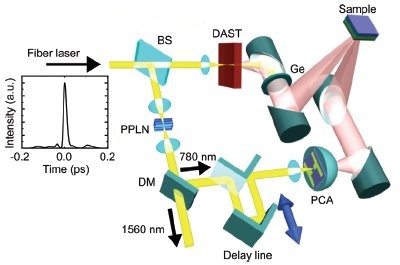
Figure 1 - Experimental setup for the fiber-laser, high-resolution time-of-flight terahertz tomography system. The inset shows the temporal waveform of the 17-fsec fiber laser. BS: beam splitter, PPLN: periodically poled lithium niobate, DM: dichroic mirror, PCA: photoconductive antenna, Ge: germanium plate.
The time-of-flight terahertz tomography experimental setup is shown in Figure 1. Output pulses from a 1.56-µm fiber laser oscillator were fed into an erbium-doped fiber amplifier. The pulses were then compressed using a large-mode-area photonic crystal fiber and a highly nonlinear fiber.14 The inset of Figure 1 shows the temporal waveform of the compressed optical pulses. The average power, pulse width, and repetition frequency of the generated optical pulses were 200 mW, 17 fsec, and 48 MHz, respectively.
The optical pulses were divided into two beams for terahertz wave generation and detection using a 50:50 broadband beam splitter. The terahertz waves were radiated from a 0.1-mm-thick DAST crystal. A germanium plate was inserted as a near-infrared filter to eliminate laser pulses transmitted through the crystal. The waves were collimated and focused onto the sample using a pair of 101.6-mm focal length parabolic mirrors whose location was optimized to achieve a minimum incident angle of 7°. The transverse resolution of the system was determined by the 0.9-mm spot size of the focused beam as measured by the knife-edge method. The terahertz pulses reflected from each layer of the sample were also focused on a 5-µm electrode gap low-temperature gallium arsenide (LTGaAs) photoconductive antenna using parabolic mirrors. The temporal waveform of the terahertz waves was traced by scanning a delay stage whereby second-harmonic generation (SHG) pulses generated with a periodically poled lithium niobate were used as probe pulses. The signal obtained was then fed into a preamplifier and detected with a lock-in amplifier. To reduce water vapor absorption effects during the tomography measurement, the terahertz wave path was purged with dry nitrogen gas.
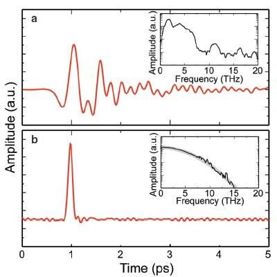
Figure 2 - Temporal waveform (a) as detected and (b) after signal processing. The insets show the corresponding Fourier transforms. The gray curve represents a Gaussian-shaped waveform.
Figure 2a shows the temporal waveform of the detected terahertz pulses with a flat aluminum mirror used as an example. The inset shows the corresponding spectrum obtained by Fourier transformation of the temporal waveform. The maximum amplitude is observed at 1 psec with several small oscillations superimposed on this peak. The corresponding spectrum extended well beyond 20 THz; its trace is not flat due to either the absorption of the DAST crystal or phase mismatching. As shown in the figure, the temporal waveform of the detected terahertz pulses was distorted compared to those radiated from a photoconductive antenna. Signal processing is therefore required to suppress the tomographic ghost images and reshape the temporal waveform. In this work, the detected temporal waveform was analyzed using a deconvolution technique whereby the signal detected with another flat mirror was used as a reference. In addition, a Gaussian window function whose bandwidth was adjusted for a 100-fsec temporal duration was used to suppress the side lobes; the resultant temporal waveform is shown in Figure 2b. The corresponding spectrum shown in the inset of Figure 2b has a Gaussian-like waveform. A single-peaked, side-lobe-free pulse was obtained. A shorter pulse was acquired by broadening the Gaussian window bandwidth, but small side peaks arose in the temporal waveform due to an inverse relationship between temporal duration and side lobe magnitude.
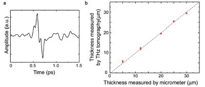
Figure 3 - Evaluation of axial resolution using PTFE films. a) Typical measured temporal waveform, and b) measured thickness of PTFE films as a function of actual thickness. The actual thickness was measured using a micrometer.
The PTFE film thickness was subsequently measured to evaluate the system's axial resolution. Figure 3a shows the temporal waveform after the deconvolution process for a 12-µm-thick PTFE film sample. Two large peaks corresponding to the front and back sides of the film are clearly observed. These peaks have opposite signs due to phase inversion by reflection at the back of the film. The film thicknesses were calculated using the delay time of these peaks and the refractive index of the film. The experimental results obtained for several thicknesses of film are summarized in Figure 3b. The horizontal and vertical axes show the actual and measured thicknesses, respectively, where a 1-µm-resolution micrometer was used to measure the actual film thickness. In this figure, film thicknesses of 5, 12, 20, 25, and 30 µm were measured correctly, that is, the axial resolution is sufficient to measure 5-µm-thick PTFE film. Since the refractive index of the PTFE film is 1.9, the resolution of this system is less than 10/n µm, where n is the refractive index of the sample.
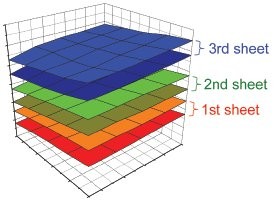
Figure 4 - 3-D terahertz tomography image of three
sheets of paper.
Lastly, terahertz tomography imaging was demonstrated. Figure 4 shows the 3-D tomography image of three sheets of 90-µm-thick paper. The front and reverse sides of each sheet can be seen clearly. With the high resolution of the system, not only are the thicknesses of the paper visible, but the gaps between the sheets can be seen as well.
References
- Kawase, K.; Ogawa, Y.; Watanabe, Y.; Inoue, H. Non-destructive terahertz imaging of illicit drugs using spectral fingerprints. Opt. Express2003, 11, 2549–54.
- Shen, Y.C.; Lo, T.; Taday, P.F.; Cole, B.E.; Tribe, W.R.; Kemp, M.C. Detection and identification of explosives using terahertz pulsed spectroscopic imaging. Appl. Phys. Lett.2005, 86, 241116.
- Ogawa, Y.; Hayashi, S.; Oikawa, M.; Otani, C.; Kawase, K. Interference terahertz label-free imaging for protein detection on a membrane. Opt. Express 2008, 16, 22,083–9.
- Fukunaga, K.; Ogawa, Y.; Hayashi, S.; Hosako, I. Terahertz spectroscopy for art conservation. IEICE Electron. Express2007, 4, 258–63.
- Mittleman, D.M.; Jacobsen, R.H.; Nuss, M.G. T-ray imaging. IEEE J. Sel. Top. Quantum Electron.1996, 2, 679–92.
- Mittleman, D.M.; Hunshe, S.; Boivin, L.; Nuss, M.G. T-ray tomography. Opt. Lett.1997, 22, 904–6.
- Fitzgerald, A.J.; Cole, B.E.; Taday, P.F. Nondestructive analysis of tablet coating thickness using terahertz pulsed imaging. J. Pharm. Sci.2005, 94, 177–83.
- Yasui, T.; Yasuda, T.; Sawanaka, K.; Araki, T. Terahertz paintmeter for noncontact monitoring of thickness and drying progress in a paint film. Appl. Opt.2005, 44, 6849–56.
- Huang, D.; Swanson, E.A.; Lin, C.P.; Schuman, J.S.; Stinson, W.G.; Chang, W.; Hee, M.R.; Flotte, T.; Gregory, K.; Puliafito, C.A.; Fujimoto, J.G. Optical coherence tomography. Science1991, 254, 1178.
- Johnson, J.L.; Dorney, T.D.; Mittleman, D.M. Enhanced depth resolution in terahertz imaging using phase-shift interferometry. Appl. Phys. Lett.2001, 78, 835–7.
- Matsui, Y.; Pelusi, M.D.; Suzuki, A. Generation of 20-fs pulses from a gain-switched laser diode by a four-stage soliton compression technique. IEEE Photon. Technol. Lett.1999, 11, 1217–19.
- Tsuchiya, M.; Igarashi, K.; Saito, S.; Kishi, M. Sub-100 fs higher order soliton compression in dispersion-flattened fibers. IEICE Trans. Electron.2002, E85-C, 141–9.
- Hori, T.; Nishizawa, N.; Goto, T. Generation of 14 fs ultrashort pulse in all fiber scheme by use of highly nonlinear hybrid fiber. In Ultrafast Phenomena XIV; Kobayashi, T., Ed.; Springer-Verlag: Berlin, 2005; pp 31–3.
- Takayanagi, J.; Kanamori, S.; Suizu, K.; Yamashita, M.; Ouchi, T.; Kasai, S.; Ohtake, H.; Uchida, H.; Nishizawa, N.; Kawase, K. Generation and detection of broadband coherent terahertz radiation using 17-fs ultrashort pulse fiber laser. Opt. Express2008, 16, 12,859–65.
Prof. Kawase, Dr. Suizu, and Dr. Shibuya are with Nagoya University, Furocho, Nagoya 464- 8603, Japan; tel.: +81 52 789 3169; fax: +81 52 789 4211; e-mail: [email protected]. Prof. Kawase and Dr. Shibuya are also with RIKEN, Sendai, Japan. The authors thank Dr. Masatsugu Yamashita of RIKEN, Dr. Toshihiko Ouchi of Caonon Inc. (Tokyo, Japan), Dr. Hideyuki Ohtake and Dr. Jun Takayanagi of Aisin Inc. (Aichi, Japan), Prof. Norihiko Nishizawa of Osaka University (Osaka, Japan), and Hirohisa Uchida of Arkley Inc. (Kyoto, Japan). This work was partially supported by a Grant-in-Aid for Scientific Research (18206009) from the Ministry of Education, Culture, Sports, Science and Technology (MEXT), Japan.