The four-channel gas analyzer described in this article includes a wireless mote (tiny microcomputer with radiofrequency transmitter) connected to a GPS chip for transmission of data to a base station computer at another location. The GPS/mote inclusion in the gas analyzer has several useful applications. If there are multiple sites to be monitored on a regular basis, the user can travel to each site and make measurements, and the locations, dates, and concentrations will automatically be transmitted and placed into a database. Real-time concentrations and location profiles of the contaminants can be produced in areas such as landfills, hazardous waste sites, fuel tank farm systems, interior air systems, and gas pipelines. Because each mote has a unique identifying number, several units can be used at different locations at the same time. This is particularly important for U.S. EPA Method 211 for large chemical and petrochemical plants that must monitor thousands of valve and flange leaks several times per year. Depending on obstructions, the motes have a range of 50–100 m. If greater distances are needed, a network of motes can be used to relay the data, and for site locations separated by miles, the base computer can be a laptop in a vehicle.
Analyzer description
Four different plug-in gas sensors can be used in the model 106 portable gas analyzer (PID Analyzers, Pembroke, MA). The handheld device has a 2-line × 16-character display, and contains a processor board; four-channel, 16-bit analog-to-digital converter (ADC) with multiplexer; pump; and battery pack. Its snap-on head enables the user to choose among more than 40 different sensors that use a variety of technologies. These include photoionization detectors (PIDs), infrared (IR) detectors, thermal conductivity detectors (TCDs), electrochemical sensors, and combustible gas (CG) sensors. The microprocessorbased analyzer calculates and displays the concentrations on its screen, and has the capability of logging more than 7000 readings manually or automatically. The stored data can be downloaded to a PC via the RS232 port and viewed with the included Grapher software.
Wireless motes
There are several commercially available wireless data collection systems with different ranges, available sensor technologies, and individual module sizes. Radiofrequency (RF) wireless motes are low-power, inexpensive transceivers that usually have, on the same board or on a separate board, some embedded sensors (e.g., temperature, humidity, light, pressure, and acceleration). They also have several analog inputs for connecting external sensors. Several applications of networks of motes have been reported, including development of a system for monitoring agricultural systems,2 and another for monitoring air quality inside of a home.3
The MICA2 radio platform (Crossbow, San Jose, CA) was determined to be the most suitable for incorporation into the model 106 analyzer. The MICA2 mote used operates on a frequency of 433 MHz and can be programmed to function with one of several plug-in boards available. These include boards with 12- or 16-bit ADCs and the board with the GPS module. The analyzer conditions the analog signals from each sensor for its on-board microcomputer, and supplies a 3.3-V voltage to two motes with the ADC board and GPS module attached to them.
As mentioned earlier, the motes have a unique ID and are configured in a mesh network that allows data transmission in hops from one mote in the field to another, and finally to a base station mote connected to a computer. The transmission from the field motes to the base mote may take any of several possible paths such that if one mote becomes disabled it does not interrupt the data flow.
System design

Figure 1 - Sensor board; MICA2 radio; and MDA320 eight-channel, 16-bit-resolution ADC board.
The MICA2 radio transmitter/receiver MPR-410 and MDA320 eight-channel, 16-bit ADC board (Crossbow) were used to collect and transmit data from the sensors of the gas analyzer to the base station (Figure 1).
The battery holder was removed, and a US1117 voltage converter (0.5” × 0.5”) was added to deliver a stable +3.3-V voltage to both boards from the internal 6-V battery of the analyzer. Due to the small size of the MICA2+MDA320 unit without the batteries, it was possible to fit the unit into a space available in the model 106 analyzer with three sensors installed—oxygen, carbon monoxide, and low-level explosives sensors (Figure 2).

Figure 2 - Model 106 analyzer with three gas sensors and MICA2+MDA320 module installed.
MoteView software (Crossbow) can be used to program the motes, operate the mesh network, store data in a database in the base computer, and display real-time data as tables or graphs. There is a set of standard precompiled applications (firmware) for different radio and sensor board combinations. The XMDA320 application had been loaded into the MICA2 module to permit the collection and wireless transmission of the data from four A/D channels on the MDA320 board. To receive the data at the base workstation, a second MICA2 module was programmed with the XMeshBase application and was connected to the computer USB port via the MIB520 USB interface board. This mesh network configuration had been tested and shown to operate successfully.
Because each MICA2 radio can operate with only one sensor board attached to it, adding the GPS module to the analyzer required a second MICA2 radio mote to collect and transmit the GPS coordinates of the board. The GPS module has a built-in step-up voltage converter to boost the +3 V available from two AA batteries on the MICA2 radio to the 3.3 V necessary for operating the GPS unit. With the US1117 voltage converter already installed in the analyzer, this second set of AA batteries was no longer needed and was removed to save space. However, connecting +3.3 V directly to the GPS module resulted in interference with the radio transmission. This effect was described earlier by Pataky,4 who resolved the issue by removing the built-in converter from the GPS module. In the present study, the built-in converter was also removed and the MICA2 and GPS module were operated directly from the +3.3-V source available in the modified model 106 analyzer.

Figure 3 - Elements of the mesh network: computer with base mote, model 106 analyzer with MICA2+MDA320 module installed, and MICA2 and GPS module.
The GPS module with the MICA2 radio does not require any signals from the gas analyzer and can operate as an independent unit, powered from two AA batteries, or can be modified as described above and connected to the +3.3-V power available from the analyzer. It can be attached to the analyzer as an option, with its active GPS antenna attached to the analyzer, or can be placed on the roof of a vehicle when scanning the work area with a moving analyzer (the antenna has a 5-m cable). Slightly increasing the dimensions of the model 106 head would allow placing the GPS module inside the analyzer as well. The GPS module has its own sensors on board, such as temperature, humidity, pressure, and 2-axis acceleration. These data are transmitted together with the GPS coordinates and can be used as desired in analysis and interpretation of the gas sensor data.
Figure 3 shows the working setup of the mesh network with the MICA2+MDA320 board installed in the model 106 analyzer, the base mote connected to the USB port of the computer, and the MICA2 and GPS module as a separate unit.
Data collection and system test
Figure 4 - a) Latitude versus time, b) longitude versus time, and c) methane concentration versus time.
The MoteView software stores the data in a POSTGRES database. The data can be exported in different formats, including an SQL (structured query language) database, SQL table, and Microsoft® Excel™ (Microsoft, Redmond, WA) worksheet. The system was tested at PID’s industrial site in a simple experiment in which the analyzer with GPS was moved from one position to another, and the calibration gas (about 2500 ppm of methane in air) was injected into the analyzer while the analyzer was at rest. The graphs of the latitude, longitude, and the gas concentration as a function of time are shown in Figure 4a–c. The horizontal parts of the graphs in Figure 4a and b, where the latitude and longitude are unchanging, correspond to time intervals in which the analyzer was not moving. Figure 4c shows the concentration of the gas injected into the analyzer as a function of time.
One mote sends the GPS coordinates as a function of time, and the other sends the gas concentrations as a function of time. Using Excel, the common times can be used to determine the gas concentration at a particular GPS location.
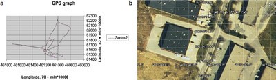
Figure 5 - a) GPS graph of position of model 106 analyzer during test, and b) satellite image of industrial site where the wireless sensor mesh network was tested.
Figure 5a shows a graph of the positions of the analyzer using latitude–longitude coordinates. A Google Earth satellite image of the industrial site is shown in Figure 5b.
The MoteView software can send particular commands from the base computer to the motes in the network. The data collection rate can be changed, and a particular mote can be rebooted or reprogrammed remotely. With an Internet connection available in the computer, the user can control the system remotely from any location in the world using, for example, the Remote Desktop™ feature of Microsoft Windows XP.
Summary
A wireless data transmission system has been integrated into the model 106 handheld, battery-operated gas analyzer. Real-time data collection and transfer from three gas sensors to the base station were achieved via RF motes in a wireless network. The wireless mote fits into the head of the analyzer that contains the sensors. A GPS module attached to the analyzer provided real-time measurements of the analyzer’s position in the field.
The wireless gas sensor system developed with the model 106 handheld gas analyzer and the Crossbow wireless motes is easy to use and can find a wide variety of applications for the real-time, automatic, multiparameter monitoring of landfills, manufacturing plants, technology processes, storage facilities, and solvent loading locations.
References
- U.S. EPA Method 21, Washington, DC.
- Wireless Agricultural Monitoring System: http://www.xbow.com.
- Chung, W.-Y.; Oh, S.-J. Remote monitoring system with wireless sensors module for room environment. Sensors and Actuators B: Chemical Jan 2006, 133(1), 64–70.
- Pataky, G. The Mote-Enabled GPS Server V2.0; Aug 2005; www.oregonembedded.com/MoteGPS.pdf.
Dr. Driscoll is with PID Analyzers, 780 Corporate Park Dr., Pembroke, MA 02359, U.S.A.; tel.: 781-709-2131; fax: 781-709-2050; e-mail: [email protected]. Mr. Hamm, Mr. Hennigar, Dr. Johnson, Dr. Perov, and Ms. Perova are with Suffolk University, Boston, MA.