Gas chromatography is a simple yet powerful technique for analyzing complex mixtures of volatile and semivolatile compounds. Comprehensive two-dimensional gas chromatography (GC × GC) has emerged recently as a high-resolution extension of conventional GC. The majority of components required to produce GC × GC separations (e.g., injectors, detectors, columns, ovens, flow controllers, etc.) are available with conventional gas chromatographs. However, a few essential items, such as the modulator and the software for visualizing 2-D chromatograms, are unique to GC × GC and hence offered by a limited number of vendors.
The modulator is a piece of hardware that transfers effluent from the exit of the primary column to the head of the secondary column as a repetitive series of pulses. The few commercially available units all employ a thermal modulation strategy1,2 that requires the consumption of large amounts of liquid cryogen coolant and gaseous working fluid. Thermal modulation produces optimal resolution but also sacrifices some of the simplicity of conventional GC. Valve-based modulation has received less attention than thermal modulation. However, valve-based modulators use straightforward, low-cost designs and do not require additional consumables. Two main classes of valve-based modulators have been developed: subsampling3,4 and differential flow.5–7 Subsampling modulators generate pulses by briefly diverting small amounts of primary column effluent to the head of the secondary column. While easy to put into practice, subsampling modulators lead to decreased sensitivity and must employ short modulation periods.8 Differential flow modulators sample all of the primary column effluent, which means that sensitivity is not sacrificed and larger modulation periods can be used. However, they also use high secondary flows that lead to elevated column pressures and limit the use of direct mass spectrometric detection.
This application note describes a simple differential flow modulator. The efficacy of this in-line fluidic modulator is demonstrated by the GC × GC analysis of the aromatic content of gasoline. The 2-D separation of gasoline has been used extensively to demonstrate modulator performance in many previously published studies.3,4,7,9–16
Experimental
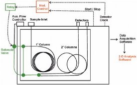
Figure 1 - Schematic of the GC × GC apparatus. Items shown in black are available from the chromatograph manufacturer. Items shown in green are available from third-party vendors and must be configured by the investigator. Items shown in red are custom-built by the authors.
Table 1 - Summary of chromatographic conditions
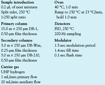
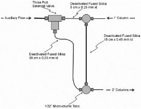
Figure 2 - Schematic of the in-line fluidic modulator.
The GC × GC system is shown in Figure 1. An Agilent 6890N gas chromatograph (Agilent Technologies, Inc., Wilmington, DE) was equipped with an Agilent 7683 series injector, electronic pneumatics, and dual flame-ionization detectors (FIDs). Sample components were partially separated on a DB-1 primary column, converted to a series of pulses by the modulator, and then further separated by passage through two parallel secondary columns. The run conditions are shown in Table 1. Agilent Technologies produced all of the columns used.
The conversion of an Agilent 6890 gas chromatograph to a GC × GC system required the addition of three custom-built components: the modulator, electronics for controlling the modulator, and software for viewing the 2-D chromatograms. A schematic of the modulator is shown in Figure 2. This device was constructed with deactivated fused-silica tubing, two tee unions (stainless steel, 100-μm-i.d. orifices, VICI, Houston, TX, part no. MT.5XCS6), and a three-port solenoid valve (Parker-General Valve, Fairfield, NJ, part no. 009-0284-900). A 20 mL/min auxiliary flow of carrier gas supplied by the gas chromatograph was connected to the common port of the three-port solenoid valve. The solenoid valve was positioned outside the column oven. The remaining modulator parts were mounted on a thin piece of stainless steel sheet metal and housed inside the GC oven. The output ports of the solenoid valve were connected to the tee unions with two pieces of 250-μm-i.d. fused-silica capillary tubing. The normally closed port of the valve was connected to the upper tee union with an 8-cm-long piece of capillary tubing. The upper tee was also the point at which the flow exiting the primary column (1 mL/min) entered the modulator. The normally open port of the valve was connected to the lower tee union with a 38-cm-long piece of capillary tubing. The two tee unions were joined by a 15 cm × 450 μm i.d. piece of fused-silica capillary tubing that served as the sample loop. A 10-cm-long piece of 250-μm-i.d. capillary tubing connected the bottom tee to a splitter union. The splitter union was connected to two secondary columns that were fed into independent flame ionization detectors.
Modulation was effected by the regular and precise switching of the solenoid valve. A custom electronic circuit was developed to control the modulator. The circuit allowed the modulation sequence to be started by the 6890 GC and to be synchronized with the detector data acquisition.
The detector signals were monitored with Agilent ChemStation software (Agilent). The resulting 1-D arrays were converted to 2-D gas chromatograms using software developed in-house.5 The 2-D chromatograms generated by the DB-Wax secondary column produced the best separations of the gasoline aromatic compounds. Thus, the chromatograms generated by the DB-210 secondary column were not used for this particular study.
A standardized gasoline sample (Spectrum Quality Standards, Houston, TX, California Phase II gasoline, catalog no. CALRR3) was analyzed with the GC × GC system. Quantitative analysis of aromatic compound classes was done with calibration curves generated by analyzing standard mixtures with the GC × GC system using a previously described procedure.16
Modulator operation
The primary function of a modulator is to convert the peaks emerging from the primary column into a series of narrow pulses suitable for further separation in the secondary column(s). The principles of differential flow modulation have been described previously in detail.5,6 Briefly, differential flow modulation generates a succession of pulses by collecting primary column effluent in a sample loop and then periodically diverting an auxiliary flow to flush the sample loop into the secondary column(s). If the auxiliary flow rate is substantially higher than the primary column flow rate, then the sample loop contents will be flushed in less time than is needed to fill the loop. The repetitive sequence of slow fill and fast flush leads to the generation of a pulse series. Under optimal conditions, the width of each pulse exiting the modulator is given by the modulation period multiplied by the primary flow to auxiliary flow ratio.
The main challenge of developing a differential flow modulator is to generate a device that can effectively combine the primary effluent and the auxiliary flow without additional peak broadening and without diminishing the primary separation. Previous studies have employed six-port diaphragm valves,5 eight-port mechanical valves,7 and a dual-loop fluidic device.6
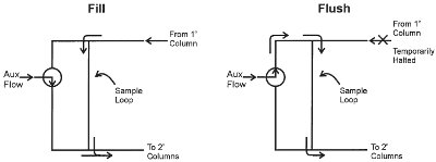
Figure 3 - Schematic of the two states of the in-line fluidic modulator. The left side of the figure shows the fill state where primary column effluent enters the sample loop while the auxiliary flow is directed to the head of the secondary column. Before the primary column effluent fills the entire sample loop, the modulator is switched to the flush state shown on the right side of the figure. In the flush state, the auxiliary flow passes through the sample loop and then to the head of the secondary column. The pressure surge generated at the head of the sample loop during the flush state temporarily stops entry of primary effluent into the sample loop.
The operating principles of the fluidic modulator described in this paper are shown schematically in Figure 3. The primary column flow enters the device at the upper tee union. The auxiliary flow enters the common port of a solenoid valve. The flow exits the valve and travels to either the tee union at the top of the device or the tee union at the bottom of the device. When the auxiliary flow is directed to the bottom union, the modulator is said to be in the fill state. In the fill state, the primary effluent flows from the top union to the bottom union through a tube that serves as the sample loop. The valve is switched prior to the primary effluent reaching the bottom union, thus putting the device into the flush state. In the flush state, the auxiliary flow travels from the top union to the bottom union. If the auxiliary flow is substantially greater than the primary flow, the contents of the sample loop are flushed from the device in a fraction of the fill time. The device is normally held in the fill state and only briefly placed into the flush state. The regular cycling of the device between the fill and flush states results in a stream of sample pulses that can be directed toward the secondary columns.
In order to minimize peak tailing, it is desirable to halt the incoming primary column flow during the flush state. This can be done by using a conduit with greater flow resistance from the three-port valve to the lower tee than the conduit connecting the threeport valve to the upper tee. The greater flow resistance of the lower conduit leads to an elevated pressure in the three-port valve during the fill state. Briefly placing the device into the inject state generates a pressure surge at the upper tee union that temporarily halts the ingress of primary column effluent.
Results and discussion
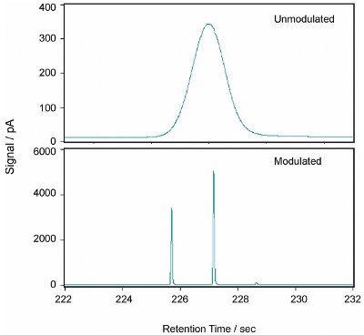
Figure 4 - Detector signal due to toluene without modulation and with modulation.
The impact of adding a second dimension of separation can be assessed by generating chromatograms with and without modulation. In the case of the fluidic modulator presented in this article, modulation can be suppressed by leaving the solenoid valve in the normally opened position. In that configuration, the primary column effluent passes through the sample loop and is continuously combined with the auxiliary flow at the head of the secondary columns. This results in the generation of a conventional 1-D chromatogram. A typical unmodulated peak is shown at the top of Figure 4. The peak is due to toluene and has a width at half maximum of 1.6 sec and a height of 340 pA.
The bottom of Figure 4 shows the same peak when modulation is employed. The controller was set to a modulation period of 1.5 sec with a fill time of 1.400 sec and a flush time of 0.100 sec. Modulation generated two major toluene peaks with widths at half maximum of approximately 65 msec. This width is in good agreement with the value predicted by multiplying the modulation period by the differential flow ratio (i.e., 1 mL/min ÷ 20 mL/min × 1.5 sec = 0.075 sec). The heights of the peaks are at least a factor of 10 greater than the height of the unmodulated peak. The increase in maximum signal intensity is due to the increased component flux caused by differential flow modulation.
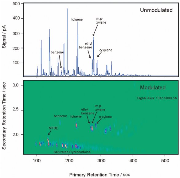
Figure 5 - Unmodulated 1-D gasoline chromatogram and modulated 2-D gasoline chromatogram.
An unmodulated 1-D chromatogram of gasoline and a modulated 2-D chromatogram of gasoline are shown in Figure 5. The benefits of GC × GC analysis are clearly demonstrated: easily interpreted chromatograms, increased detector response, clean separation of the aromatic compounds from the saturated compounds, and group separation of aromatic compounds according to the number of carbon atoms.
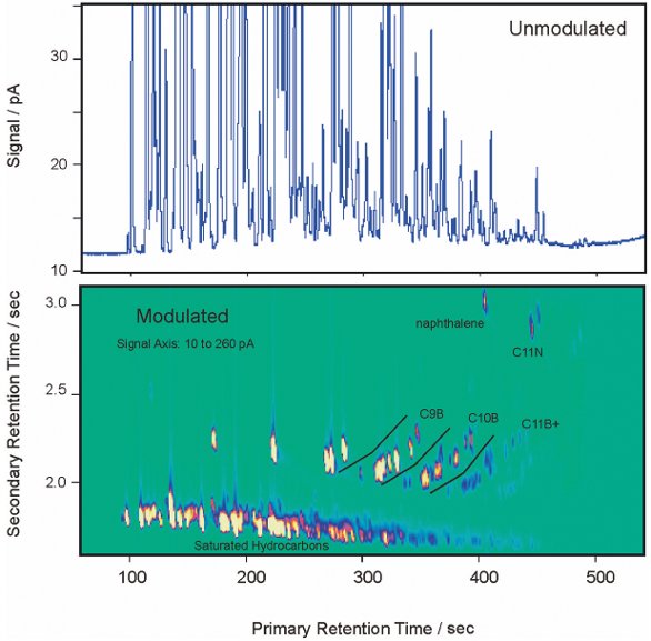
Figure 6 - The chromatograms shown in Figure 5 with the scale of the signal axis reduced by a factor of 20. The aromatic compounds are separated into bands with equal carbon number. The bands of the alkylbenzenes are designated as follows: C9B = monoaromatics with nine total carbon atoms; C10B = monoaromatics with 10 total carbon atoms; C11B+ = monoaromatics with 11 or more total carbon atoms; C11N = diaromatics with 11 total carbon atoms.
In order to observe the minor gasoline constituents, the scale of the signal axis of both chromatograms was reduced by a factor of 20 in Figure 6. The 1-D chromatogram has substantial peak overlap throughout the chromatogram that causes the peaks of the minor components and the baseline to be obscured. The lack of a clear baseline makes accurate quantitation difficult.
The 2-D chromatogram has some overlap within the bands of compound classes (e.g., saturated hydrocarbons and aromatic compounds with the same carbon number) but the baseline is present in the unpopulated regions in the secondary dimension. This allows for accurate quantitation of the compound classes.
Table 2 - Results for California Reference Gasoline compared to reported results for ASTM Methods D5580 and D5769, and the GC-MS analysis
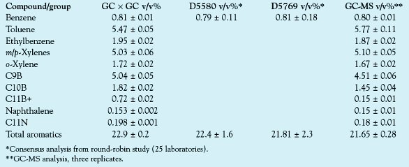
Calibration curves were generated for the 10 aromatic compound classes listed in Table 2. In each case, the five-point calibration curves produced linear regressions with R2 values greater than 0.9994. Replicate analysis (n = 6) of the standardized gasoline generated total peak areas for the compound classes that had relative standard deviations that were less than 2%. The measured aromatic composition of the gasoline is shown in Table 2. The values obtained with GC-MS using ASTM Method D576917 are also shown in Table 2 along with multilaboratory values of benzene and total aromatic content determined by ASTM Methods D558018 and D5769.17 The GC × GC values are in excellent agreement with the GC-MS values, and the precision of the results is similar. The GC × GC results for benzene and total aromatics are within the range of values determined by ASTM Methods D5580 and D5769.
Conclusion
The in-line fluidic modulator described in this paper produces 2-D separations that are similar to those produced by previously described differential flow modulators. However, the modulator has a wider temperature range than diaphragm valve modulators and has a simpler construction than the dual-loop fluidic modulator. In addition, the in-line fluidic modulator maintains optimal performance over a wider range of differential flow ratios than the dual-loop fluidic modulator. The simplicity and low resource requirement of the modulation strategy decreases the difficulty of implementing comprehensive 2-D gas chromatography and can potentially lead to the broader adoption of the GC × GC technique.
References
- Ledford, E.B.; Billesbach, C. Jet-cooled thermal modulator for comprehensive multidimensional gas chromatography. Hrc-J. High Res. Chromatogr.2000, 23, 202–4.
- Beens, J.; Adahchour, M.; Vreuls, R.J.J.; van Altena, K.; Brinkman, U.A.T. Simple, non-moving modulation interface for comprehensive two-dimensional gas chromatography. J. Chromatogr.A2001, 919, 127–32.
- Bruckner, C.A.; Prazen, B.J.; Synovec, R.E. Comprehensive two dimensional high-speed gas chromatography with chemometric analysis. Anal. Chem.1998, 70, 2796–2804.
- Hamilton, J.F.; Lewis, A.C.; Bartle, K.D. Peak amplitude and resolution in comprehensive gas chromatography using valve modulation. J. Sep. Sci.2003, 26, 578–84.
- Seeley, J.V.; Kramp, F.; Hicks, C.J. Comprehensive two-dimensional gas chromatography via differential flow modulation. Anal. Chem. 2000, 72, 4346–52.
- Bueno, P.A.; Seeley, J.V. Flow-switching device for comprehensive two-dimensional gas chromatography. J. Chromatogr. A2004, 1027, 3–10.
- Diehl, J.W.; Di Sanzo, F.P. Determination of aromatic hydrocarbons in gasolines by flow modulated comprehensive two-dimensional gas chromatography. J. Chromatogr. A2005, 1080, 157–65.
- Seeley, J.V. Theoretical study of incomplete sampling of the first dimension in comprehensive two-dimensional chromatography. J. Chromatogr. A2002, 962, 21–7.
- Beens, J.; Boelens, H.; Tijssen, R.; Blomberg, J. Quantitative aspects of comprehensive two-dimensional gas chromatography (GC × GC). Hrc-J. High Res. Chromatogr.1998, 21, 47–54.
- Kinghorn, R.M.; Marriott, P.J. Comprehensive two-dimensional gas chromatography using a modulating cryogenic trap. Hrc-J. High Res. Chromatogr.1998, 21, 620–2.
- Phillips, J.B.; Gaines, R.B.; Blomberg, J.; van der Wielen, F.W.M.; Dimandja, J.M.; Green, V.; Granger, J.; Patterson, D.; Racovalis, L.; de Geus, H.J.; de Boer, J.; Haglund, P.; Lipsky, J.; Sinha, V.; Ledford, E.B. A robust thermal modulator for comprehensive two-dimensional gas chromatography. Hrc-J. High Res. Chromatogr. 1999, 22, 3–10.
- Frysinger, G.S.; Gaines, R.B.; Ledford, E.B. Quantitative determination of BTEX and total aromatic compounds in gasoline by comprehensive two-dimensional gas chromatography (GC × GC). Hrc-J. High Res. Chromatogr.1999, 22, 195–200.
- Pursch, M.; Eckerle, P.; Biel, J.; Streck, R.; Cortes, H.; Sun, K.; Winniford, W. Comprehensive two-dimensional gas chromatography using liquid nitrogen modulation: set-up and applications. J. Chromatogr. A2003, 1019, 43–51.
- Harynuk, J.; Gorecki, T. New liquid nitrogen cryogenic modulator for comprehensive two-dimensional gas chromatography. J. Chromatogr. A2003, 1019, 53–63.
- Harynuk, J.; Gorecki, T. Comprehensive two-dimensional gas chromatography in stop-flow mode. J. Sep. Sci.2004, 27, 431–41.
- Micyus, N.J.; McCurry, J.D.; Seeley, J.V. Analysis of aromatic compounds in gasoline with flow-switching comprehensive two-dimensional gas chromatography. J. Chromatogr. A2005, 1086, 115–21.
- Method D5769; ASTM International: West Conshohocken, PA, 2003, vol. 05.02.
- Method D5580; ASTM International: West Conshohocken, PA, 2003; vol. 05.02.
Dr. J.V. Seeley is Associate Professor, and Ms. Micyus is Graduate Fellow, Oakland University, Department of Chemistry, Rochester, 2200 N. Squirrel Rd., Rochester, MI 48309, U.S.A.; tel.: 248-370-2329; fax: 248-370-2321; e-mail: seeley@oakland. edu. Dr. J.D. McCurry is Senior Applications Chemist, Agilent Technologies, Inc., Wilmington, DE, U.S.A. Dr. S.K. Seeley is Associate Professor, Kettering University, Department of Science and Mathematics, Flint, MI, U.S.A. The authors would like to thank Agilent Technologies, Inc., for lending the 6890N gas chromatograph used for this study.