Over the years there have been a number of efforts to build solid-state viscosity sensors for both laboratory and on-line applications that would measure smaller sample sizes, as well as be easier to use and maintain than conventional rotary viscometers. Because viscosity is a measure of the resistance of a liquid to flow, traditional viscosity measurements require that either the sensor mechanism or the liquid be in motion. For practical purposes, this makes it extremely difficult to measure the viscosity of the very small samples of blood, biological fluids, and pharmaceuticals that need to be tested in many laboratories.
Temperature, shear rate, and other variables—which can be very different off-line and on-line—can significantly change the viscosity of the liquid being sampled. This difference can be critical when conducting real-time tests and experiments in which it is critical to detect changes in viscosity as they occur during an experiment or test, making measurements from a baseline rather than simply measuring absolute values.
In an effort to address this problem and develop instrumentation that could be integrated or embedded into both laboratory equipment and process machinery to measure the viscosity of small samples, the viscosity of liquids that are being heated or cooled, or the viscosity of liquids flowing through laboratory equipment or process machinery, Sandia National Laboratories (Albuquerque, NM) has developed two prototype acoustic wave sensors. One approach used a quartz crystal device and tracked resonance damping and frequency shift with an advanced electronic circuit. The second approach employed a quartz plate as a waveguide and combined the sensing mechanism of the quartz crystal device with the wafer-scale manufacturing technology used in the production of surface wave sensors.
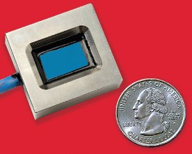
Figure 1 - Solid-state acoustic viscometers can be used to measure samples as small as 100 μL, outputting real-time flow, time, yield, and temperature data to a computer, control system, or handheld reader.
Additional research was funded by both the Department of Defense and the U.S. EPA. Building on this base, commercial manufacturers refined this technology to overcome challenges in design, manufacturability, and measurement range. This effort resulted in the development of monolithic piezoelectric sensors. These multireflective, solid-state acoustic wave devices combine the features of resonators and delay lines to offer a wide dynamic range (air to thousands of centipoise), overcoming the major pitfalls of the earlier prototype designs (see Figure 1). They also have the built-in communications capabilities necessary to output real-time data to a computer via a USB port or handheld reader so that laboratory personnel can have a real-time picture of flow behavior and plot flow, time, yield, and temperature curves.
These sensors combine solid-state surface chemistries with ultrasensitive acoustics. In addition, since there are no spindles or moving parts, they are easy to clean, immune to shock, and capable of withstanding vibrations of 30 G or more. Slightly larger than a matchbox, the sensors are hermetically sealed so that they are completely immersible in a laboratory beaker or larger vessel. They can also be embedded in laboratory or production equipment and networked to control systems.
Measurements are made by placing the quartz crystal wave resonator in contact with a liquid. In practice, liquid can be dropped on the face of the sensor from a pipet, the sensor can be immersed in a laboratory beaker, or the sensor can be incorporated into a laboratory or pilot processing line to measure the viscosity of a liquid as it is being processed. The liquid’s viscosity determines the thickness of the fluid hydrodynamically coupled to the surface of the sensor. The sensor surface is in uniform motion at frequency ω = 2ΠF with amplitude U. Both frequency and amplitude are determined by the electronics. As the shear wave penetrates into the adjacent fluid to a depth, d, power is transferred from the quartz crystal to the liquid. Acoustic viscosity is calculated using power loss from the quartz resonator into the fluid.
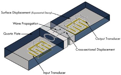
Figure 2 - Cutaway view of quartz crystal sensor with propagated waves.
The acoustic wave resonator supports a standing wave through its thickness. The wave pattern interacts with electrodes on the lower surface—hermetically sealed from the liquid—and with the fluid on the upper surface. The bulk of the liquid is unaffected by the acoustic signal. Only a thin layer—on the order of microns or micro inches—is coupled to the sensor and measured by its vibrating surface (Figure 2).
There are a number of different measurements of viscosity. The most familiar are kinematic viscosity (centistokes) and dynamic or absolute viscosity (centipoise). These two measurements are related as centistokes equal centipoise/specific gravity. Acoustic sensors measure viscosity in units of centipoise × specific gravity. This measurement is based on the transfer of acoustic shear wave energy from a quartz crystal or other solid waveguide having characteristic impedance. The square of the power loss of the acoustic wave passing through the fluid is proportional to the product of frequency, density, and viscosity. Since the frequency is known, the sensor measures viscosity × density.
Knowledge of specific gravity allows conversion of one measurement to another when shear rate and temperature are equal. Thus, the digital output of an acoustic wave sensor can be automatically displayed in cup seconds or centipoise units if the specific gravity (density) of the fluid is known.
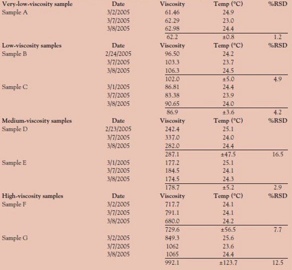
Preliminary testing has shown with an acoustic wave viscometer that the sensor can differentiate between different samples and have very good reproducibility, even though the data are not compensated for temperature. Table 1 shows that the acoustic sensor was able to measure the various topical creams with reproducibility values ranging from 1.2% to 16.5%. A next-generation solid-state viscosity sensor operating at a lower frequency will provide greater accuracy in measurements while further improving mid- to high-viscosity range performance.
Table 1 - Solid-state viscometer measurements of various topical creams
Part 2 of this article (https://www.americanlaboratory.com/914-Application-Notes/35147-From-Desert-Storm-to-Lipstick-Applying-Viscosity-Measurement-to-New-Challenges/) will discuss some of the many applications in which solid-state viscometers can save time in laboratory testing, improve quality control in the process industries, and reduce maintenance costs, while ensuring equipment reliability in stationary engines and transportation equipment.
Mr. Durdag is CEO, BiODE, Inc., 100 Larrabee Rd., Westbrook, ME 04092, U.S.A.; tel.: 207-856-6977; fax: 207-856-6864; e-mail: [email protected].