Since the early to mid-1940’s, scientists using infrared spectroscopy have been trying to obtain spectral data from ever smaller samples. Starting with micro-KBr pellets and then beam condensers and micro-MIR (multiple internal reflectance) accessories, the ability to obtain a spectrum from an extremely small sample has been attempted on a regular basis.
The introduction of FTIR spectrometers in the mid-1960’s stimulated the interest in infrared microscopy due to the increased throughput of the interferometer and the ability to perform multiple scans to increase the signal-to-noise ratio. Infrared microscope systems were initially introduced in the late 1970’s and early 1980’s by Digilab and Spectra-Tech. The IRPlan was introduced in 1983 by Spectra-Tech as an FTIR microscope accessory that could be interfaced with instruments from various manufacturers. With the ability to collect infrared spectra from samples as small as 15 μm in either transmission or reflection mode, the infrared microscope accessory became the preferred tool for the collection of infrared spectra from sample areas of 250 μm or less.
There are numerous applications for FTIR microscopy, including polymer and fiber analysis, pharmaceutical and materials analysis problems, forensics, semiconductors, biochemistry, and chemical analysis applications. For almost any sample that can be scanned with a traditional infrared method, the FTIR microscope can be used to collect an infrared spectrum from a fragment of a sample. The spatial resolution of an infrared microscope is primarily determined by the diffraction limit of the infrared wavelengths used for analysis, usually 12–20 μm. The aperture system in the microscope is used to control the spatial dimensions of the sample beam, and this aperture cannot be smaller than the infrared wavelengths to be focused onto the sample.
FTIR microscopes are a compromise between the desire to visually image the sample, much like a refractive microscope using glass objectives, but with the ability to transmit and reflect infrared radiation. Since the midinfrared wavelengths do not transmit through glass, the cassegrain reflection objective is used to focus the infrared source energy small enough to illuminate the microscope sample while minimizing losses of infrared energy. Infrared and visual beam paths are combined somewhere within the body of the microscope such that a visual image of the sample can be used for focusing and positioning of the sample and the infrared beam can be used for collection of the sample spectrum. Cassegrains are reflective objectives with primary and secondary mirrors. These objectives can provide an extremely small focal plane with minimal distortion of the source energy. The sample is imaged through the cassegrain objective, brought into a visual focus that matches the infrared focal point, and then the sample data are collected using the infrared optical system. Dual cassegrain elements are required to focus and then defocus the infrared beam for transmission measurements using the rest of the microscope optical train to conduct the source energy to the sample and onto the integrated detector.
A sample aperture is used to exclude portions of the sample outside the area of immediate interest. The aperture is positioned somewhere in the plane of the infrared beam, and the aperture dimensions are used to define the sample area for collection of both the background and sample spectra. The combination of an FTIR microscope with an FTIR instrument can provide a powerful analysis method for samples that cannot generally be examined using traditional methods of analysis. Traditionally, FTIR microscopes have been large accessories interfaced using an external beam from the FTIR instrument. This arrangement requires additional optics, a dedicated detector, and extended bench space. While useful, these systems can be expensive compared to traditional sample accessories such as diffuse reflectance or attenuated total reflectance (ATR) accessories that fit into the standard instrument sample compartment.
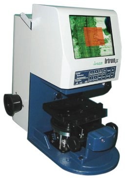
Figure 1 - Irtron μ sample compartment microscope accessory.
The Irtron μ (Figure 1) (Jasco, Easton, MD) is an FTIR microscope accessory that fits into the instrument sample compartment of the FT/ IR-4000 or FT/IR-6000 series instruments (Jasco). The Irtron μ integrates a manual stage, chargecouple device (CCD) video camera, and LCD video screen in an interchangeable accessory that weighs no more than 15 lb and utilizes the standard instrument detector(s) for data collection.
The microscope can collect sample data with either the standard deuterated triglycine sulfate (DTGS) or an optional liquid nitrogen cooled mercury cadmium telluride (MCT) detector for collection of infrared spectra. The microscope accessory can be used to collect spectral data from 15,000 to 250 cm–1, depending on the instrument configuration. With the accessory, samples as small as 20 μm can be visualized, and spectral data can be collected using either transmission or reflection mode. The addition of an ATR objective, such as diamond, germanium (Ge), or zinc selenide (ZnSe), allows the collection of ATR spectra from samples, minimizing the requirement for extensive sample preparation.
The Irtron μ can be integrated with the instrument power supply and PC software, or can be operated in a standalone mode using a separate power supply and front panel controls for the collection of either background or sample spectra, while additional controls are used to set the size of the sample aperture or Aperture Through Observation System (ATOS). This sample aperture system, which is illuminated by an integrated red LED, can be set as small as 20 × 20 μm or as large as 800 × 800 μm.
Applications
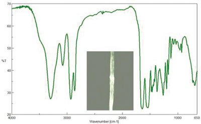
Figure 2 - Irtron μ spectrum and CCD image capture (inset) of a nylon fiber, 25 × 100 μm, MCT detector, 128 scans at 4 cm–1 resolution.
Figure 2 illustrates a spectrum of a simple nylon fiber that was collected using the Irtron μ accessory. The fiber was flattened and mounted across an open aperture on the standard sample holder for the microscope. The sample fiber was visualized using the visible system, the ATOS aperture was set to exclude areas other than the fiber, the fiber was moved away from the aperture, and the background of an open area was collected. The fiber was then moved into the aperture area, and the sample spectrum of the fiber itself was collected.
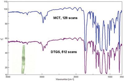
Figure 3 - Polyester fiber (inset—CCD video capture),4 cm–1 resolution; comparison of instrument detector performance.
Figure 3 demonstrates a comparison between the MCT and DTGS detector performance for a polyester fiber sample. The sample was flattened and mounted over an open aperture on the standard sample holder. The ATOS aperture was set to 35 × 80 μm and the data were collected with the two different detectors. As illustrated in the figure, the DTGS detector is capable of providing similar quality data for the same sample, but does require a greater number of scans, and time, to obtain the same quality data as the MCT detector.
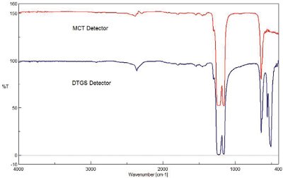
Figure 4 - DTGS and MCT detector scans of a PTFE film sample, 128 scans, 4 cm–1 resolution, 100 × 100 μm aperture.
For samples that contain functional groups that absorb outside the range of a standard MCT detector, the DTGS detector can provide an advantage for these measurements given that the DTGS detector has a greater spectral range down to 400 cm–1. Figure 4 illustrates a comparison between the spectra of a thin film sample of poly(tetrafluoro-ethylene) (PTFE) sample collected using the two different detectors. The DTGS detector was able to obtain the peaks associated with the C–F bending modes below 550 cm–1, while the MCT detector spectral range is limited to approx. 600 cm–1. While it is possible to specify an MCT detector with a greater spectral range, there is a sacrifice in sensitivity performance with this detector and often it is elected to obtain a medium-band or narrow-band MCT with the attendant restricted spectral range.
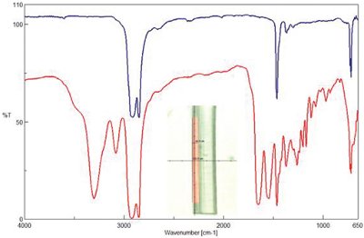
Figure 5 - Polymer laminate sample, 256 scans, 4 cm–1 resolution, polyethylene (top) and nylon (bottom) polymer layers.
Figure 5 demonstrates the spectra collected from the cross-section of a polymer laminate sample. The spectrum of the polypropylene layer was collected using the ATOS aperture set to 20 × 700 μm; the nylon layer was larger and the aperture was set to 50 × 700 μm for the spectrum collection. The DTGS detector was used to collect the spectra of the polymer layers. The spectra demonstrate the ability of the ATOS aperture to exclude the portions of the nylon layers that are on either side of the polyethylene layer in the laminate sample.
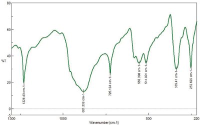
Figure 6 - GeO2 crystal sample, 256 scans, 4 cm–1 resolution, DTGS detector.
When the FTIR is configured with a CsI beamsplitter, the spectral range of the instrument can be extended into the far-IR region approaching 200 cm–1. Figure 6 illustrates the spectrum of a germanium oxide crystal that has several absorption bands below 600 cm–1. The GeO2 crystal was supported on a polyethylene sheet, the band at 725 cm–1 due to the polyethylene. The data were collected with a standard DTGS detector, which can obtain data from organometallic samples, well beyond the range of even a wide-band MCT detector used in standard FTIR microscope systems.
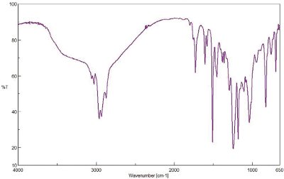
Figure 7 - Reflectance scan of beverage can lining, 128 scans, 4 cm–1 resolution.
To obtain reflectance spectra, the top cassegrain optic was used; infrared source energy was directed through one-half of the cassegrain, and the other half was used to collect the reflected energy and direct it onto the detector. The sample aperture was set as desired for the sample, a background spectrum was collected from a reference mirror, and the desired sample area was collected as a sample spectrum and ratioed versus the background spectrum of the reference mirror. In Figure 7, the reflectance spectrum of a soda can lining is displayed; the spectrum was collected with the MCT detector and an aperture setting of 100 × 100 μm. The results of a library search provided a similar spectrum that was a two-part epoxy compound.
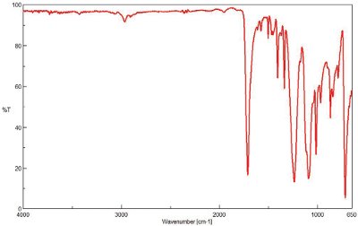
Figure 8 - ZnSe ATR objective spectrum of layer in a polymer laminate sample, 256 scans, MCT detector, 250 × 250 μm.
The addition of an ATR objective provides the capability to collect sample spectra with a minimum of sample preparation. Figure 8 demonstrates a spectrum of a polymer laminate sample collected using a ZnSe interchangeable ATR objective and the MCT detector. The active sample contact area for the ATR objective was 250 μm; the poly(ethylene terephthalate) sample was much larger than the active area of the ATR objective.
Conclusion
The Irtron μ is an FTIR microscope accessory that truly is an accessory. Capable of being easily set into the instrument sample compartment, the microscope requires no alignment and can utilize either the standard DTGS detector or a liquid nitrogen cooled MCT detector. With the ability to collect transmittance, reflectance, or ATR spectra of many different types of samples, the Irtron μ offers a range of capabilities without compromise in performance.
Dr. Larsen is Scientific Applications Manager, and Mr. Carriker is Spectroscopy Products Manager, Jasco Inc., 8649 Commerce Dr., Easton, MD 21601, U.S.A.; tel.: 410-822-1220; fax: 410-822-7526; e-mail: [email protected].