In almost any laboratory or research and scientific facility, there are numerous devices, instruments, or processes that require gases to run the instrumentation or process or to calibrate the devices. Gas cylinders that are located in the laboratory area can present significant hazards, and the space they take up can be better used for other more appropriate purposes. Gas delivery systems that are properly designed, sized, and located can improve safety in the laboratory. In addition, attention to high-purity requirements—purity, compatibility, flow, materials of construction, and more—is vital for safety, performance, and cost-efficiency.
There are a number of codes and standards that apply to the storage, use, and installation of gases and their delivery systems. This article is not meant to detail them all, but will reference portions of those standards and codes as they apply to the general principles of gas storage and delivery systems.
The codes and standards that are most significant are:
- National Fire Protection Association NFPA 55: Compressed Gases and Cryogenic Fluids Code
- Compressed Gas Association CGA P-1: Safe Handling of Compressed Gases in Containers
- OSHA Standards 29 CFR 1910.101: Compressed Gases General Requirements.
Laboratories must understand and follow these codes and standards thoroughly in order to comply with the minimum requirements of any gas system.
Gas requirement audit
The first step in properly designing any gas installation, whether it is for a new facility or a retrofit, is to conduct an audit or survey of the gases required for each location or laboratory. Identifying what gases are required for each instrument, their purity level, required delivery pressure, and peak flow demand is essential in determining everything from the size of the piping required, to the storage area required, and even the mode or source in which the gas may be supplied. Overestimating the pressure or flow requirements can result in higher installation costs and reduced gas savings resulting from residual contents left in cylinders or higher monthly rental fees on cylinders that are not required. Underestimating, however, can cause inefficient supply of gas to critical instruments or systems that impair their use or operation.
Using a simple form, like that shown in Figure 1, for each lab or use point allows the total requirement of each gas to be determined for that area, and when compiled as a whole will determine the scope of the building’s needs. The total volume of each gas required for an average week or month’s operation can then be compared to the options available for that gas to be delivered by the gas supplier.
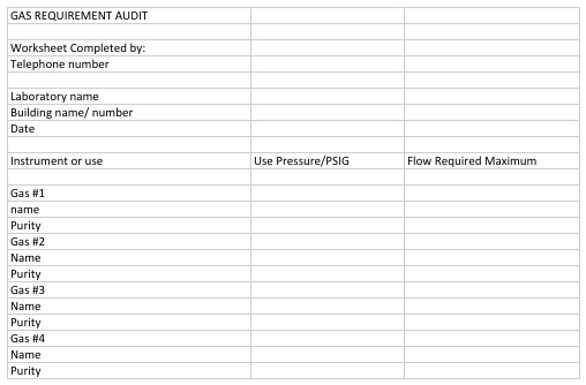
Figure 1 - Gas requirement audit form.
While some gases or purities can only be supplied in high-pressure cylinders such as helium with a purity of 99.999% used for gas chromatographs, others—such as argon with the same purity for use by an inductively coupled plasma analyzer—can be supplied in high-pressure cylinders or cryogenic liquid cylinders that equal the volume of as many as 18 high-pressure cylinders. The total number of cylinders required to supply the laboratory for no less than an average week’s usage will then be the ideal number of cylinders connected as the primary supply, with an equal number of cylinders connected as the reserve supply and an additional number as backup. This will then assist in determining the space and location required for the gas delivery system and cylinder storage area.
Selecting a location for storage and gas delivery systems
There are some very specific storage and separation requirements for the areas in which compressed or cryogenic gases are stored and/or connected to a building’s gas delivery system. They may vary by local code requirements, but at a minimum must meet those of NFPA codes and OSHA standards. As a minimum, gas cylinders should be stored and secured in an upright position using brackets, chains, or straps in a well-lit and ventilated area away from combustible materials and sources of heat or ignition. The gases should be separated by hazard type as detailed in NFPA 55 Table 2-1.5, “Separation of Gas Cylinders by Hazard.” Space should be allowed to segregate full from empty cylinders with the appropriate hazard notification signage as required under Chapter 4 of NFPA 55.
Regarding the storage requirements for hydrogen, there are additional distances from other hazards that must be met. These are now listed under the current edition of NFPA 55, as included in chapters as shown in Figure 2. They were previously listed separately under NFPA 50-A, “Standards for Gaseous Hydrogen Systems at Consumer Sites.” Of note is the separation of hydrogen storage or use areas from other flammable or combustible liquids of at least 20 ft from ignition sources or ordinary electrical equipment of at least 25 ft, and 50 ft from air-compressor intakes, ventilation intakes, or air-conditioning intakes. This also limits the total amount of gas allowed based on where it is located. Where that allows inside storage, systems containing less than 3000 ft3 must be located in “special rooms” that are of sturdy construction and made of noncombustible material. Walls must have a minimum 2-hr fire rating, with at least one wall in an outside location. In general, the preferred location of hydrogen systems is outside the building where there are no wall openings above the system, with any wall openings separated from the storage area by at least 25 ft.
If dealing with oxygen storage where it is defined as a “bulk oxygen installation” with a volume of more than 20,000 ft3, there are additional restrictions that must be followed, as detailed in NFPA 55. These are now included as chapters, though at one time they were listed separately under NFPA 50, “Standards for Bulk Oxygen Systems at Consumer Sites.” In general, bulk oxygen systems are not permitted to be located inside buildings; thus when the total volume of oxygen for a system exceeds 20,000 ft3, the storage location must be outside the building.
Pipe sizing and flow considerations
When determining what size pipe or tubing to use for a specific application, the main consideration is to determine what the maximum required flow for that specific gas would be if all application or use points were flowing to their maximum at the same time. This can be found by totaling the individual use points and applying a conservative safety factor to allow for growth of requirements of at least 20–50%, depending on what the future outlook is for that gas.
In addition, when sizing the piping, the total distance to the very last use point in the piping run must be considered. If the total flow is measured over distance, then there will be a pressure drop from what the initial inlet pressure is to what the pressure is over that distance. In general, the maximum pressure drop should be no more than 10% of the primary inlet pressure. The maximum pipeline pressure would be equal to the highest required pressure for the use point of that specific gas or instrument, plus a minimum of either 20% or 25 psig, depending on the flow requirement for that use point. It may be higher, depending on how far the piping run is.
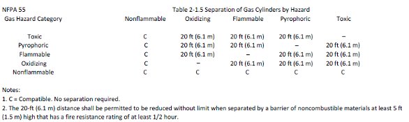
Figure 2 - Hazard distance requirements.
A useful tool is the pipe size chart shown in Figure 3. It gives the maximum flow of air for various pipe sizes with either a 10 or 5% pressure drop. The chart can be found under the resources category at www.concoa.com. As an example of how to use this information, if flowing at an initial inlet pressure of 100 psig, through a ½” diameter pipe, one can expect to flow 3240 ft3 with over 100 ft of piping with a 10% drop in pressure at that point. In other words, 90 psig can be delivered to that use point with that flow rate, if it was the only connection on the system. One would, however, specify the gas delivery system to be delivering a minimum of 120–125 psig into the pipeline to allow for individual control of the delivered pressure at each point of use, including the one requiring 90 psig. Since piping use points should also have reverse flow check valves, especially those for flammable gases like hydrogen or oxygen, the cracking pressure of these check valves also needs to be considered.
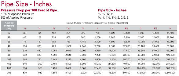
Figure 3 - Pipe size chart.
Choosing the right gas delivery system
For almost all laboratory gases, maintaining gas purity is a critical requirement. To that end, the choice of materials of construction and their compatibility with that specific gas and its purity level must be considered. It is not enough that the materials are compatible with the specific gas, but that the design ensures and retains the purity of the gas. From the inlet to the outlet, a system that is designed with either bar stock brass or 316L stainless steel components is desired over forged components. Any diaphragms should be made of 316L stainless steel, and the diaphragm seals should be of a metal-to-metal design.
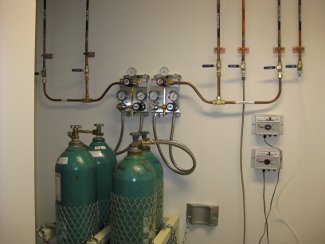
Figure 4 - Laboratory switchovers with the highest leak integrity.
The system should have minimum leak integrity of 1 × 10⁻⁸ standard cm3/sec of helium, which equals the volume of a cubic centimeter escaping or entering over 3.1 years. This not only ensures that gas will not leak out of the system, but also that impurities will not be allowed to enter the system and compromise the purity of the gas. For the inlet of the system, the inlet connections should have reverse flow check valves in the cylinder connections such that once the system has been put into service, the amount of any ambient air that may enter is limited to a very small amount. Two such systems are shown in Figure 4.
The gas delivery system should be capable of delivering the maximum required pressure and flow as described above and the information determined from the gas audit.
Though there are many other areas that must be considered, the primary areas of concern are where to locate the gas storage area outside the laboratory, how much gas will be required, and how the gas will be delivered to the end use points. Users who follow these guidelines are well on their way to selecting a safe and cost-effective gas delivery system.
Larry Gallagher is Specialty Gas Products Manager, CONCOA, 1501 Harpers Rd., Virginia Beach, VA 23454, U.S.A.; tel.: 800-225-0473; e-mail: [email protected].