The newly released revised standard for laser diffraction particle size analysis, ISO13320:2009, contains valuable advice for those seeking to optimize their use of the technique. This article examines each aspect of the measurement process, from instrument selection through results analysis.
As noted in the introduction to ISO13320:2009, laser diffraction is now the dominant method of particle size distribution analysis. Fast and nondestructive, the technique can be applied to an array of particulate systems, wet or dry, and lends itself to full automation. For many, laser diffraction analysis is now simply a case of loading the sample and pressing a button. However, successfully reaching this point, for any specific application, requires understanding and considering a range of factors, such as instrument hardware, measurement methodology, results verification, and optical model selection.
The new version of ISO13320 replaces the standard version released in 1999, ISO13320-1, and has been completed following a comprehensive five-year review. Instrument users and manufacturers alike were proactive in seeking a revision, following a decade of significant advances. Commercial technology leaders have been involved from the outset, helping to shape the standard as a superior source of information about all aspects of the technique. The result is a valuable resource that promotes more efficient, accurate, and reproducible measurement. This article reviews important changes to the standard and their practical relevance in the optimal use of laser diffraction.
Instrument design
Understanding the principles of operation that underpin all laser diffraction systems is a good starting point for an examination of hardware differences. A sample passing through a beam of collimated light scatters it at an angle and intensity that are dependent on particle size. Smaller particles scatter light at relatively low intensity to wide angles, while large particles scatter more strongly at narrow angles. A laser diffraction analyzer detects the scattered light pattern from a sample and converts it to a particle size distribution using an appropriate optical model of light behavior.
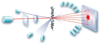
ISO13320-1 focused on the use of the forward Fourier optical setup (the classic setup) in which the lens is placed after the measurement zone. This optical arrangement was extremely common in instruments developed during the 1980s and early 1990s. In contrast, ISO13320:2009 highlights advances in the technology, particularly with respect to the measurement of very fine particles, delivered by the reverse Fourier setup. It establishes reverse Fourier, in which the lens is positioned before the measurement (as shown above), as a standard design for laser diffraction systems, presenting the advantages and limitations of each alternative.
A conventional Fourier arrangement gives a wide working range, beneficial, for example, in spray analysis. Conversely, with a reverse Fourier setup, measurement pathlength is restricted, but scattered light is detectable over a wider range of angles, providing access to a broader dynamic range and better resolution. Extending capabilities in the submicron range is especially valuable since the trend in most industries is toward increasingly fine products.
The new standard retains 0.1–3000 µm as the overall size range for which laser diffraction systems are applicable. It also lists hardware features that improve analysis within this range, and in special cases extends it below 0.1 µm, including:
Figure
1 - Hardware of a laser diffraction analyzer, which includes: light
source(s), beam processing unit, Fourier lens, and multielement
detector.
- An extra light source of different wavelength
- One or more off-axis light sources
- Scattered light detectors at less than 90° but larger than the conventional range (forward scattering)
- Scattered light detectors at angles greater than 90° (backscattering).
Figure 1 is a schematic of the Mastersizer 2000 design (Malvern Instruments, Malvern, Worcestershire, U.K.), which includes some of these features—a supplementary blue light source, and off-axis and light detectors at angles up to 135°. These provide a wide dynamic range and very high resolution across all size fractions.