Miniaturization has allowed for the development of a myriad of microfluidic platforms that offer a host of advantages over conventional analytical techniques, including small sample volume requirements, portability, fast sampling times, the ability to multiplex, and compatibility with other techniques.1 Applications incorporating microfluidics include cell sorting, microreactor technologies, polymerase chain reaction (PCR), protein crystallization, and small-molecule derivatization.2–9
The use of magnetic polymeric particles with surface functional groups has been applied to many areas of chemistry, biology, and medicine. For example, magnetic microspheres have been used in thermotherapy for cancer cells, immunoassays, cell separation, DNA hybridization, protein and peptide separation, and pathogen detection.10–16 Their simple separation and conjugation with a wide array of biomolecules has led to their integration in various detection methods. Microbeads have a high density of surface functional groups, making them easy to modify and thereby making it possible to use higher concentrations of samples, leading to an increase in limits of detection (LOD). A variety of surface chemistry modifications are available for magnetic microbeads. Furthermore, microbeads come in a wide variety of sizes (diameters), making them amenable to micro total analysis systems (µTAS) vis-à-vis microfluidics. The most important advantage of magnetic microsphere-based analysis is easy separation of bound complexes from unbound detectable species without the use of sophisticated and expensive techniques and instrumentation.
This paper describes some of the authors’ work in microfluidic bead-based assays and enzymatic microreactions.17–21 Specifically, several novel assays utilizing microfluidic chips to assess the binding of teicoplanin (Teic) from Actinoplanes teichomyceticus, immobilized on magnetic microspheres to D-Ala-D-Ala terminus peptides, are described.
In the first technique, frontal analysis microchip capillary electrophoresis (FAMCE) is used to examine the binding of Teic, covalently attached to magnetic microbeads, to small peptides. Direct and competitive assays are demonstrated. The binding constants obtained from the FAMCE technique are comparable to those values using affinity CE, fluorescence spectrometry, and flow cytometry. In the second technique—microchip frontal affinity chromatography (MFAC)—an electrokinetically controlled microfluidic system containing two magnetic microbead columns fabricated into the microchannels is used to estimate the binding of a small peptide to magnetic microbeads derivatized with Teic. One column is filled with Teic-modified beads and is used as the affinity column. The second column contains nonderivatized beads and is used as the control. The extent of interaction between the peptide and the two types of beads in either microchannel resulted in differences in the migration time of the ligand, and this is used in the Scatchard analysis to obtain a value for the binding constant. In a third technique, an enzyme-catalyzed microfluidic assay using magnetic microbeads is described. Here, diaphorase (DI) (E.C. 1.6.99) is covalently attached to magnetic microbeads and is integrated into a short section of a microchip fabricated from polydimethylsiloxane (PDMS). DI converts nonfluorescent resazurin to fluorescent resorufin in the presence of nicotinamide adenine dinucleotide phosphate (NADH). In this work, an embedded magnet holds the microbeads in place within the microchannel while a solution of resazurin and NADH in buffer is flowed through the beads.
Experimental
Materials
5-Carboxyfluorescein-D-Ala-D-Ala-D-Ala (DA3) was custom-synthesized by Anaspec (San Jose, CA). Glycidyl methacrylate (GMA), dimethylacrylamide (DMA), tetramethylethylenediamine (TMED), Nα,Nε-diacetyl-lys-D-Ala-D-Ala (DA2), N-[2- hydroxyethyl]piperazine-N′-[2-ethanesulfonic acid] (HEPES), Tween-20, 2-(N-morpholino)ethanesulfonoic acid (MES), resazurin sodium salt, bovine serum albumin (BSA), NADH and N-(3-dimethylaminopropyl)-N′-ethylcarbodiimide hydrochloride (EDC), and DI (E.C. 1.6.99) from Clostridium kluyveri were obtained from Sigma (St. Louis, MO). Zinc chloride, MES, potassium chloride, and dialysis tubing with 3500 mol wt cutoff were obtained from Fisher (Pittsburgh, PA). Negative-type photoresist SU-8 2025 and its developer were obtained from Microchem (Newton, MA). Sylgard 184 PDMS oligomer and its cross-linking agent were obtained from Dow Corning (Midland, MI). Carboxylic group terminated Dynal® magnetic beads M-270 (~2.8 µm diam) were obtained from Invitrogen (Carlsbad, CA). Teicoplanin (Teic) was obtained from Advanced Separation Technologies (Whippany, NJ).
Instrumentation
Equipment and fabrication of microchip
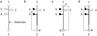
Figure 1 - a) Schematic of microchip, and b–d) MCE protocol. The process for injecting the supernatant solution, rinsing the channel, and injecting the external standard is represented by b–d. Arrows indicate the solution movement; 1 and 2 are buffer wells, 3 is the waste well, 4 is the supernatant well, and 5 is the external standard well.
Microfluidic chip electrophoresis (MCE) studies were performed on a laboratory-built microfluidic system consisting of two high-voltage power supplies and a confocal laser-induced fluorescence (LIF) detector. Briefly, a laser beam was horizontally focused into the microchannel. In the vertical direction, fluorescence was detected by a photomultiplier tube after passing through two filters and two objectives.
The PDMS chips were prepared by using a mold created by soft photolithography.21 The pattern (Figure 1a) was designed using AutoCAD software (San Rafael, CA) and printed as a high-resolution (20,000 dpi) photomask (CAD/Art Services, Inc., Bandon, OR). Negative-type photoresist was spin-coated onto a 3-in. silicon wafer at 1200 rpm for 30 sec. Sylgard 184 PDMS prepolymer was mixed thoroughly with its curing agent at 10:1 (v/v), degassed, and then baked for 2 hr at 75 °C. The PDMS replicas were peeled off from the mold. Holes (3 mm diam) were made for the buffer and sample wells by punching through the PDMS chip. The channels were 25 µm high and 50 µm wide at the top. The distances from wells 1, 2, 4, and 5 to well 3 were 5.0, 4.8, 4.0, and 5.0 cm, respectively (Figure 1a). The PDMS replica was irreversibly sealed onto a clean substrate glass of 2-mm thickness after being treated with oxygen plasma.