While a Fourier transform infrared (FTIR) spectrophotometer provides a number of benefits relative to a scanning IR spectrophotometer, a significant disadvantage of an FTIR system is that the presence of water vapor and/or CO2 in the sample chamber will lead to additional peaks in the observed spectrum. These peaks may obscure peaks that provide important information about compounds in the sample and can be eliminated by sealing the sample chamber, followed by purging with dry, CO2-free air (purge gas). The importance of purging the sample chamber and interferometer can be readily seen in the spectra shown in Figures 1 and 2; the unpurged sample (Figure 1) exhibits significant noise in the region from approximately 2000 to 1400 cm–1 and a sharp peak is observed at 2400 cm–1. When the sample chamber and interferometer are purged for 2 min (Figure 2), the sharp peak is eliminated and the noise is nearly gone.
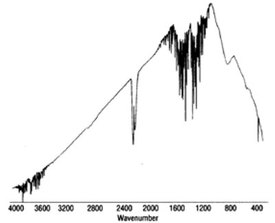
Figure 1 - FTIR spectrum collected without purging the sample compartment.
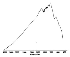
Figure 2 - FTIR spectrum collected after 2-min purge with purge gas.
While some analysts use a high-pressure air or nitrogen tank or a source of liquid nitrogen for CO2-free gas and a dessicator to ensure dryness, an increasingly popular alternative is an inhouse purge gas generator. An in-house purge gas generator removes the interfering materials from compressed laboratory air and ports the purge gas directly to the spectrophotometer. This paper describes the design of an in-house purge gas generator for FTIR and describes a number of benefits to the end user. The inhouse purge gas generator provides a dramatic increase in safety and convenience with a decrease in cost relative to the use of tank gas or liquid nitrogen. In addition, in-house generation of the purge gas is significantly more energy efficient than other methods of supplying the purge gas.
A schematic diagram of a typical inhouse purge gas generator is shown in Figure 3. The in-house purge gas generator (Parker Balston model 75-52, Parker Hannifin Corp., Haverhill, MA) (Figure 4) produces dry CO2-free air from a standard compressed air supply (inlet pressure maximum is 125 psi) and includes the following components:
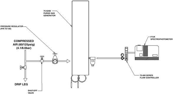
Figure 3 - Design of a typical purge gas generator.
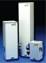
Figure 4 - Parker purge gas generators.
a) A robust, high-quality coalescing filter element that removes particulate matter such as dust, pump oil, and water particles. The filter removes 99.99% of particulates that are >0.01 μm and is designed to withstand the dynamic changes in pressure, temperature, and airflow that occur on a regular basis in a typical compressed air system.
b) A pressure swing adsorption (PSA) system that passes the filtered air into a chamber that contains molecular sieves to remove the nondesired components of the input air and port the dry CO2-free gas to the final filter (c), while returning the CO2 and water vapor to the atmosphere. The purge gas generator includes two chambers so that purge gas is constantly being generated. One chamber is generating purge gas while the other chamber is being regenerated by heating it at a reduced pressure to remove the gases that have been collected by the molecular sieves during the generation of purge gas. A moisture monitor is included to ensure that the purge gas is sufficiently dry.
c) A high-efficiency filter after the PSA system is employed to ensure that any particulate matter in the purge gas that may have been carried over from the molecular sieves is not allowed to enter the sample compartment of the spectrometer.
A molecular sieve composed of an activated carbon (charcoal) is used in the PSA system because it has a very large surface area for adsorption of the undesired gases. The molecular sieve is extremely porous and can retain a significant amount of the gases before it must be purged. Due to its high degree of microporosity, 1 g of activated carbon has a surface area in excess of 500 m2 (which is equivalent to the area of about two tennis courts), as determined by nitrogen gas adsorption experiments.
The 75-52NA purge gas generator fits on a laboratory bench and can provide purge gas at a maximum flow rate of 88 SCFH (34 lpm) at an inlet pressure of 125 psig (8.6 barg) (similar units are available with a maximum inlet flow of up to 264 SFCH [102 lpm]). The maximum flow rate of purge gas is dependent on the inlet pressure; at a typical inlet pressure of 80 psig (5.5 barg), the purge gas flow rate is 60 SCFH (23 lpm). The CO2 concentration of the purge gas is <1 ppm, and the dewpoint is –100 °F (–73 °C).
Benefits of providing the purge gas with an in-house generator
An in-house purge gas generator provides a number of important benefits compared to the use of tank gas, including minimizing safety hazards, increasing convenience, reducing the overall cost of operation and decreasing the environmental impact. Because an in-house system provides such significant advantages, many manufacturers of FTIR systems co-market in-house purge gas generators with their spectrometers.
Minimizing safety hazards
When an in-house purge gas generator is employed, only a small amount of the gas is present at a low pressure at a given time and the gas is ported directly to the FTIR spectrometer. As an example, the model 75-52NA generates a maximum of 72 SCFH (34 lpm) of purge gas at a maximum pressure of 125 psig. In contrast, a number of serious hazards exist when purge gas is supplied to the instrument via a high-pressure tank that may have a pressure of >2000 psi. In addition, significant hazards such as the possibility of injury or damage during the transport and installation of a gas tank are eliminated by the use of the purge gas generator. A standard tank is quite heavy and can become a guided missile if the valve on a full tank is compromised during transport (in many facilities, specially trained technicians are used to replace gas tanks). Additionally, the use of a pressurized tank can lead to a significant hazard in earthquake-prone areas.
Convenience
An in-house purge gas generator can provide gas on a 24-hour/7-day-a-week basis without any user interaction other than a minimum of routine annual replacement of the coalescing prefilter and occasional replacement of the moisture-indicating cartridge. In contrast, when tank gas is employed, the user must pay close attention to the level of gas in the tank and replace the tank on a periodic basis, which can be a time-consuming operation. If the gas in the tank is exhausted, the timely collection of useful spectra may be compromised, and if the FTIR is collecting data on an unattended basis, important data may be lost.
Robertet Flavors (Piscataway, NJ) has employed purge gas generators for over 10 years, according to Dr. Rajesh Padya, Assistant Director of Quality Assurance. These systems operate on house air and require no servicing, except for annual filter replacement, which takes approximately 30 min per system. In this facility, the house air is passed through a catalytic converter to remove hydrocarbons and is also used with the GC-FID (flame ionization detection) system in the laboratory.
In many facilities, spare purge gas tanks are stored outside in a remote area for safety reasons, and it is time consuming to obtain a replacement tank. When this is necessary, the analyst may require an individual who is qualified to handle the tanks. Many users have indicated that replacing used tanks can be a significant inconvenience, especially in inclement weather if the tanks are stored outside or if not properly secured when the laboratory is located in a seismic zone.
If there is a need to replace a tank during a series of analyses, the analyst must interrupt the analytical work to restart the system, wait for a stable baseline, and may have to recalibrate the system. In addition, if a series of automated analyses is desired (i.e., on an overnight or weekend basis), the analyst must ensure that sufficient volume of each gas is on hand before starting the sequence.