In many research and pharmaceutical facilities, there are requirements for delivering carbon dioxide gas for cell culture incubator applications or bioreactor operations. For large-scale operations, the gas is delivered in bulk form and stored outside in large cryogenic tanks. In medium to even some larger operations, it is delivered in transportable cryogenic liquid containers commonly referred to as liquid cylinders or dewars; for smaller operations it is delivered in 50-lb-content high-pressure cylinders. Typically, liquid cylinders are installed inside of the building. As with their larger bulk units, they have relief valves that vent excess pressure. High-pressure CO2 cylinders are also normally located inside the facility.
 Figure 1 – Vertical cross-section of a typical liquid cylinder.
Though the cylinders technically contain much of their 50-lb content in liquid form, it is maintained in that liquid state by its own vapor pressure of 830 lb per square inch (psig) at normal room temperature. This pressure increases or decreases in relation to the cylinders’ ambient temperature, but in general there is no risk of their venting gas when not in use. High pressure cylinders do not have relief valves, but rather each cylinder valve has a burst disk that protects against extreme pressure that would only be seen if the cylinder were subjected to elevated temperatures in a fire or similar event. This is in contrast to bulk or transportable liquid cylinders, where the liquid CO2 is actually stored in a cryogenic state at –57 °C (–70 °F) inside the tank or container, insulated from the ambient outside temperature with a vacuum-insulated barrier that maintains it in that state with a vapor pressure that is much lower than high-pressure cylinders, typically less than 350 psig. Figure 1 shows the features and cross-section of a typical liquid cylinder.
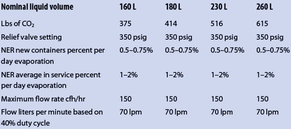
However, though the initial pressure may be as low as 145 psig, that pressure increases over time as more of the liquid is changed to gas inside the container at a rate referred to as the Normal Evaporation Rate (NER) of 1–2% per day of its contents, until the pressure inside reaches the relief valve setting of 350 psig, at which time the relief device opens and releases some of that pressure. Unless gas is withdrawn or used at or above that rate, the relief will periodically actuate to maintain the pressure below the relief valve setting of 350 psig. Table 1 shows the typical contents’ relief valve setting and NER for liquid cylinders, and points out that any container not in use or not installed consuming gas at that rate may be venting 1–2% of its contents every day.
Table 1 – Typical contents’ relief valve setting and NER for liquid cylinders
Inasmuch as CO2 is the prime “greenhouse” gas, such setups beg significant questions in terms of the laboratory environment:
- What steps can be taken to avoid excess venting?
- Since CO2 does not support life, what is the safety risk of its presence in the laboratory?
- What is the solution to mitigate that risk?
This article explores these issues and what can be done to optimize the “green” state of your facility’s CO2 system, as well as its safety. As with any requirement for gases in a laboratory, this will begin by evaluating the amount of CO2 your specific installation requires for its daily operation and the options for supplying that demand. Once the total volume of CO2 for daily operation has been determined, it will define what form bulk, portable liquid cylinders, high-pressure cylinders, or a combination of those options you would need to maintain an uninterrupted supply of CO2 to the processes, given supplier delivery, space, and storage limitations.
The article will also define what type of gas delivery system to consider and how to integrate systems that can reduce excess venting, and at the same time monitor and reduce the safety risk venting may present with regard to creating an oxygen deficiency in your facility.
Evaluating CO2 requirements
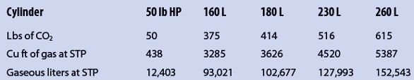
The first step in any properly sized laboratory or facility’s gas requirement is to determine the daily demand for that gas. If this involves an existing ongoing operation, it would begin by totaling the amount of gas containers onsite and considering how many are delivered each week or month to start with a baseline of what your facility has on hand in total gas in use and that held in reserve. From that information, you can determine the total gas on hand using the information in Table 2, which gives the average full contents of both high-pressure and cryogenic liquid cylinders in pounds of net content converted to liters of gas at standard temperature and pressure. This can be compared to what the expected daily consumption of gas should be once you evaluate each use location for the entire facility. From this you can determine whether to consider changing the gas delivery system and form of supply, and if you can reduce the amount of CO2 unnecessarily released through venting to become a greener laboratory. For new operations, each use location should also be evaluated to determine the total expected daily requirement for CO2. From this, the best gas delivery system and form of delivery can be determined.
Table 2 – Average full contents of both high-pressure and cryogenic liquid cylinders in pounds of net content converted to liters of gas at standard temperature and pressure (STP)
In the case of CO2 for cell culture incubators or bioreactors, you should evaluate the flow requirement during normal operation. For cell culture incubators, this requirement is typically expressed in liters per minute (lpm) of CO2 flow at 6 lpm for each incubator chamber. Keep in mind a dual-stack incubator would be twice this rate when counting the number of incubators. However, the CO2 to cell culture incubators, though required to be uninterrupted, is not a continuous 24/7 flow. The CO2 is used to maintain the required concentration inside the chamber at typically 5% with the balance being air or, in some cases, a reduced ambient level of oxygen content by also injecting nitrogen to lower the oxygen content. The CO2 concentration only changes when the incubator door is opened, exposing the chamber to ambient air with very little CO2 content (<400 ppm).
Once the door is closed, the incubator’s CO2 monitor detects that lowered concentration and actuates a solenoid to allow more CO2 to flow into the chamber to return the concentration back to 5% (or the programmed concentration). Then that solenoid shuts off the gas flow until the concentration is reduced through consumption by the cell culture’s biological processes (relatively minimal over time), or until the door is opened again and the process begins anew. The actual time the CO2 is flowing for each door opening is relatively short; it typically takes as little as 20 sec of gas flow to return the concentration to the required 5% level.
Table 3 – Evaluation of duty cycle vs total daily CO2 demand to aid in calculating net pounds of CO2 required for supplying demand
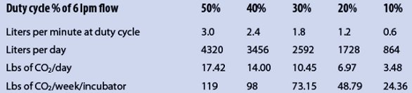
The key to comparing the flow of 6 lpm of gaseous CO2 per incubator must be weighed against the duty cycle of how often the door is opened in an hour of daily use compared to how often the door remains closed over that 24-hr period. For very active operations, this may be as often as once every 5 min during operating hours; less active operations may be as little as once an hour. Determining the duty cycle is therefore critical to evaluating what each incubator’s average daily consumption of CO2 should be. In general, based on years of experience, the author typically assigns a duty cycle of not more than 30% to active operations and not less than 10% for minimally active operations. Table 3 compares an evaluation of duty cycle to the total daily CO2 demand, based on 6 lpm of flow that can be used to then calculate demand in net pounds of CO2 required for supplying that demand.
For bioreactors, the demand, though required to be uninterrupted during operation of the reactor’s batch or cycle, is not required to be available 24/7, but rather only during duration of use. Typically this demand is expressed in pounds of CO2 per cycle or pounds per hour of duration of the cycle. Therefore, determining your daily demand is somewhat easier by simply totaling the pounds required per batch or cycle and how many of these the facility does during an average day. By using the information in Table 2, you can determine if your operation is of the size where cryogenic liquid or less likely a high-pressure cylinder is an option, or if the total demand requires a bulk installation.
Gas delivery system evaluation and options
Typically, if a building site allows for and can be piped for CO2 service during construction and the demand is greater than 1000 lb/day, then bulk becomes the obvious option, and your gas supplier should be consulted for sizing and locating the bulk installation. If demand is less than 1000 lb/day or if your usage points or location will not allow for a bulk installation, other forms of supply such as a liquid cylinder can be considered. The piping system and the supply manifold can then be sized such that a safe and efficiently green supply can be determined by making sure that the available supply supports your requirements while limiting or eliminating the vent loss posed by relief valves on these containers.
As with any bulk or sizable liquid cylinder installation, area oxygen deficiency monitors should be installed in storage or use areas, and any pipeline-relief valves should be piped to an appropriate exterior vent line as per NFPA 50 and building safety code requirements. The relief valves on cryogenic liquid cylinders cannot be piped away and are exempt from this requirement. For this reason it is critical that the gas delivery system be sized properly and incorporates an “economizer” program to minimize the vent loss of any liquid cylinders that sit unused on the reserve side of the system.
 Figure 2 – A gas switchover system automatically switches to a reserve bank of cylinders once the primary side has been emptied for efficiency and cost-effectiveness.
To provide a continuous and uninterrupted supply of CO2 to either incubators or bioreactors from cryogenic liquid cylinders or high-pressure cylinders, an automatic switchover manifold similar to that shown in Figure 2 is usually employed. These systems automatically switch to a reserve bank of cylinders once the primary side has been emptied. For installations in which this supplies a single incubator or small number of incubators, the supply may be as few as one to two 50-lb high-pressure cylinders per side and operate on what is called a pressure-differential basis.
In these installations there is no risk of venting CO2 since there are no relief valves, other than those on the pipeline or system that only actuate if the pressure control fails. If the demand for your operation is greater than 200–300 pounds of CO2 per week, then you should consider using cryogenic liquid cylinders as the primary source of supply, and either high-pressure or liquid cylinders as the reserve supply. In this instance, a pressure-differential system should not be considered because it may result in false switching from a partially full liquid cylinder, since the pressure in these cylinders can vary with demand and can result in as much as 30% of their contents not being used. This will result in that volume of gas eventually being vented to the atmosphere as gas, either as it sits awaiting the next delivery or is vented by the supplier once it is returned to the supplier’s facility. Figure 3 shows a top-down view of the various valves, safety mechanisms, and component parts of a typical cryogenic liquid cylinder.
 Figure 3 – Overhead view of a liquid cylinder.
Failure to utilize 30% of the gas purchased is not what one would consider responsible “green operations” in terms of the environment and cost-efficiency. It is responsible to ensure that the system employs a means to accurately determine when the liquid cylinder is empty by using a computer-controlled algorithm to monitor if an increase in the primary side’s pressure occurs once a changeover to the reserve side has taken place, which indicates residual contents that can be used. This in itself can improve your green rating by as much as 20–30%, and means that all but 2–3% of the CO2 purchased is being used.
The other most important thing to determine is that your facility justifies using cryogenic liquid cylinders as the reserve and that the system also includes an economizer feature that monitors the pressure in the reserve cylinders and switches to draw gas off those containers before they reach the relief-valve setting of 350 psig and are prevented from venting CO2 into the surrounding area. As previously discussed, this venting can be as much as 2% per day of the contents of the container for a single-reserve liquid cylinder, which can be as much as 7–8 lb of CO2 per day. By employing a system that includes an economizer program, this can be reduced or effectively eliminated.
Clearly, it is important that, when sizing your system using liquid cylinders, the total number of containers online both as primary and reserve supply is adequate to supply your facility for at least a week of usage, but that the total daily NER based on 2% of their total contents is less than your daily expected usage. Doing so as closely as possible ensures that your required daily demand is satisfied, and also that, with the use of an appropriate system, the amount of CO2 released by the container’s relief valves is minimized or eliminated as much as possible. Your facility is then as green and safe as possible, given its requirement for CO2.
Larry Gallagher is Specialty Gas Products Manager, CONCOA, 1501 Harpers Rd., Virginia Beach, VA 23454, U.S.A.; tel.: 800-225-0473; fax: 757-422-3125; e-mail: [email protected].