A liquid chromatographic system with
a mass spectrometric detector (LC-MS)
requires a supply of nitrogen as
the curtain gas, pure zero grade air as
the source gas, and dry (–40 °F dewpoint)
air as the source exhaust gas.
In many facilities, these gases are
provided by a series of compressed
gas tanks; while the use of gas tanks
can meet the overall requirements of
the system, this approach imposes a
number of serious operational, safety,
and economic disadvantages. From
an operational standpoint, the tanks
must be replaced periodically, requiring
operator involvement and reducing
the overall uptime of the system.
In addition, the handling of compressed
gas tanks introduces a significant
safety risk and is an expensive
way to supply the necessary gases.
A considerably safer, more convenient,
and cost-effective method of
providing the necessary gases is via
in-house gas generation. An in-house gas generator is a compact system
that can be located in the facility
directly alongside the LC-MS system
and operate on a continuous basis
with a minimal amount of operator
interaction. This paper describes how
gas generation systems can provide
the various gases from laboratory
air, discusses the benefits that arise
from their use, and portrays a number
of cases in which significant benefits
have been achieved from self-generation
of the gases.
In-house generation of gases such as nitrogen, zero air, and source exhaust
air from laboratory air involves a number
of discrete processes to separate the
various components of air into a series
of gas streams of the desired purity that can be directly ported into the LC-MS.
A variety of gas generation systems
are available that can provide a single
component (e.g., nitrogen), and many
facilities acquire a generator for a single
gas since the other gases (e.g., dry air)
may already be available in the facility.
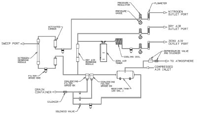
Figure 1 - Schematic representation of Parker Balston model LCMS-5000 tri-gas generator. (Reprinted with permission from Parker Balston Source LC/MS TriGas Generator Series Model LC-MS 5000 Technical Bulletin, 2006.)
In recent years, the various components
of gas generation systems have
been integrated into a single system
to generate the assorted gases that
provide all of the gases required for
LC-MS. This offers a significantly
greater degree of convenience, system
control, and cost savings for the chromatographer.
The general design of
an integrated system (Parker Balston
model LCMS-5000 tri-gas generator
[Parker-Hannifin Corp., Filtration
and Separation Div., Haverhill,
MA]) is presented in Figure 1 (gas
generation systems that are designed
to provide only one of the gases [e.g.,
nitrogen] contain only those components
relevant for generation of the
desired gas).
The input for the generator is laboratory
air, which is divided into three
streams to generate the desired gases.
The generator includes the following
major components to produce the
various gases:
- Compressor—pressurizes ambient
laboratory air to 110–140 psi (7.5–9.6 bar). An oil-less rotary scroll
compressor is employed, which
consists of two identical spirals offset
180° with respect to the other so
that the scroll mesh is used to compress
the air. An after-cooler cools
the temperature of the discharged
air. The cooling serves to extend
the system life and condenses much
of the water in the compressed air,
which is sent to an electric drain
trap and is automatically discarded.
- Coalescing filters—remove additional
water and particulate matter
(as small as 0.01 μm) from the
compressed laboratory air. Drains
collect the liquid that is accumulated,
and automated valves allow the liquid to be sent to waste. This
filter protects the hollow fiber
membrane that generates nitrogen
(see below) and associated components
from contamination that
may foul the operation.
- Activated carbon module—removes
hydrocarbon contaminants that may be present in the air. One module is
located before the hollow fiber membrane,
and a second carbon module
is located after the hollow fiber membrane
to ensure that research-grade
purity gas is supplied to the instrument.
A filter is placed after the carbon module
to trap any carbon particles.
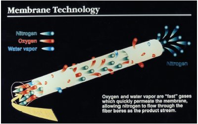
Figure 2 - The hollow fiber membrane bundle separates nitrogen from air. Oxygen and water vapor permeate the membrane, allowing nitrogen to flow through the tubes. (Reprinted with permission from Parker Balston Analytical Gas Systems Bulletin AGSB, 2006, p. 32.)
- Hollow fiber membrane bundle (for
nitrogen)—consists of a series of hollow
fiber membranes that permit oxygen
and water vapor to permeate it
and escape through the sweep port
while the nitrogen flows through the
tube, as shown in Figure 2. While each
individual fiber membrane has a small
internal diameter, a number of fibers
are bundled together to provide an
extremely large surface area for permeation
of oxygen and water. After
the membrane bundle, the nitrogen
passes through another carbon filter
and is allowed to flow directly to the
outlet port at a flow rate of up to 10 L/min at a pressure of 80 psi.
- Dryer membrane (for dried air)—permits water vapor to permeate the hollow fibers of the membrane,
resulting in dry air. A small portion
of the dry air is redirected along the
fibers to sweep out additional water
vapor. Dried air from the dryer membrane
is allowed to flow directly to
the outlet port. Air with a dewpoint
of –40 °F is delivered at a flow rate of
28 slpm at a pressure of 100 psig.
- Catalyst module (for zero air)—oxidizes
hydrocarbons into CO2 and
H2O. A coiled copper after-cooler
and fan are employed to cool the
hot outlet air. The cooled zero air
passes to the zero air outlet port at a
flow rate of up to 23 L/min at a pressure
of 110 psig.
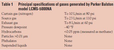
The detailed specifications of the various
gases provided are summarized in
Table 1. The in-house gas generator
can supply a continuous stream of the
requisite gas(es) for the LC-MS system
at the flow rate and pressure necessary
to maintain operation of an LC-MS
system, and systems are available to
provide the necessary gases for a single
or two LC-MS systems.
Operation of an in-house gas generator
is straightforward. Once the
system is installed, no day-to-day
maintenance or user interaction is
required. The system contains no
moving parts, except for the compressor.
On a periodic basis, the filters
should be replaced; typically they
are replaced after approx. 5000 hr
of operation or on a yearly basis to
ensure optimum performance.
Comparing in-house
generation of gases with the use of tank gases for LC-MS
An in-house gas generator offers a
number of significant benefits to the
operator of an LC-MS system relative
to the use of tank gas. These include
a dramatic improvement in safety, a
reduction in the inconvenience of
changing and handling tanks, and a
significant lowering of the cost of supplying
the gases.