Check valves are a vital mechanical component of HPLC pump hardware. A detailed description of check valve function and hardware designs is given in Ref. 1. Briefly, a pair of check valves (an inlet and an outlet) prevents flow from a high-pressure area into the low-pressure area inside of the HPLC pump head. As a result, the pump’s piston is capable of delivering a mobile phase flow through the column at high pressure. “A properly functioning check valve must open and close quickly and easily, and must provide a secure seal over a wide pressure range.”1
By definition, check valves in HPLC pumps are exposed to repeated mechanical stress at high pressure. Therefore, this device is more predisposed to failure than other HPLC pump parts, such as pistons or piston seals. While check valves are susceptible to malfunction, it may be difficult to identify. HPLC diagnostic tests accurately detect different kinds of external leaks associated with a pump pressure drop. Unfortunately, the detection of internal pump leaks is more complicated because they do not lead to a substantial pressure drop, and are therefore unrecognized by diagnostic algorithms used in HPLC software programs.
The authors noticed this problem during operation of a high-throughput multidimensional LC-MS system.2 They observed that the analyte retention time very slowly but steadily increased about 10% in this application; however, hardware diagnostic tests were passed successfully. Such an effect cannot be explained by column deterioration and, as expected, a column swap was not helpful. This problem was resolved by replacing the outlet check valve in pump head B (delivering organic solvent) of the Agilent 1100 binary HPLC pump (Agilent Technologies, Palo Alto, CA). Of note, replacement of the check valve in pump head A had no impact on retention time (data not shown).
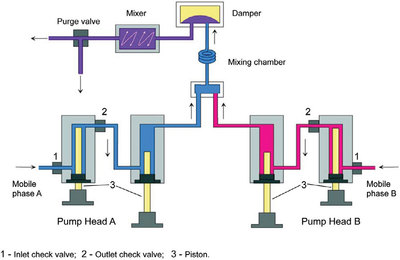
Figure 1 - G1312A binary pump flow path diagram. (Copyright 2004, Agilent Technologies, Inc. Reproduced with permission. Agilent Technologies, Inc. makes no warranty as to the accuracy or completeness of the foregoing material and hereby disclaims any responsibility therefore.)
The Agilent 1100 series binary pump G1312A consists of two identical solvent delivery channels (pump heads) A and B. Each pump head utilizes two pistons for solvent delivery, and inlet and outlet check valves (Figure 1). To identify possible pump malfunction, the pressure test (PT) and leak test (LT) are available as part of ChemStation software (Agilent). The pressure test uses only channel A to increase pressure up to 390 bar, and then the pump flow is shut off. The anticipated pressure drop should be no more than 2 bar/min. This test is efficient for evaluating external leaks; however, internal leaks may still occur and escape detection. For example, 12 used outlet check valves were tested. For some of them, the PT passed successfully, while the LT failed. The LT is more specific for internal leaks. During this test, each piston delivers 3 μL/min for 30 sec; the obtained pressure profile should be horizontal (plateau) or slightly positive. In other words, the test fails if there is a negative pressure slope, meaning 100% loss of delivered isopropyl alcohol. Internal leaks, where the pressure profile is flat and not decreasing, is considered acceptable by the ChemStation diagnostic method/algorithm. An internal leak occurs when solvent delivered by the piston 1 stroke partially flows back to the solvent reservoir (bottle) via a malfunctioning inlet check valve. Alternatively, solvent delivered by the piston 2 stroke partially flows back into chamber 1 via a malfunctioning outlet check valve. When piston 2 makes its delivery, chamber 1 under atmospheric pressure fills up, and backflow from the high-pressure to the low-pressure chamber 1 occurs. Internal leaks result in the actual flow rate delivered by the pump head, being less than the value preset by the software. The flow, delivered by pump, can be measured by a flowmeter. Theoretically, minor internal pump leaks can be detected by an accurate flowmeter installed after a flow restrictor (such as capillary tubing). However, a liquid flowmeter is a very costly device that is not frequently used in the analytical laboratory due to synchronization issues. Therefore, internal leaks are diagnostically challenging to detect.
As mentioned above, increased retention time can be explained by an internal leak of mobile phase in pump head B (which delivers organic solvent). Such a leak can occur from the delivering pump head chamber 2 into the metering pump head chamber 1. Backflow is also possible if the ball-seat of the outlet check valve is damaged. Hence, less organic solvent is delivered by the pump to the column, resulting in an increase in retention time. Another possibility for retention time increase is a leak from chamber 1 though an incompletely closed inlet check valve. Theoretically, if the mechanical wear of pump head A is higher than pump head B (which results in more internal leaks), such circumstances will decrease the analyte retention time. Such drift, in turn, may be wrongly interpreted as the result of column deterioration.
Since minor internal leaks cannot be detected by a generic HPLC diagnostic test, a series of performance tests was conducted in order to design a troubleshooting protocol of potential check valve solvent delivery problems. Experiments were performed on an Agilent 1100 series binary pump G1312A and UV monitor G1314A.
The authors propose the following approach. After pump maintenance or repair, 30-min gradient runs at the same flow rate should be performed using water as mobile phase A and water/0.1% acetone as mobile phase B. Instead of a column, a pressure restrictor should be installed. The authors used 1.5 m long × 65 μm i.d. PEEK tubing (p#1560, IDEX/Upchurch, Oak Harbor, WA), which served as a virtually zero-dead-volume flow restrictor. This tubing generates ~250 bar backpressure at 0.5 mL/min. Next, the time required to reach half maximal absorbance signal was calculated from the UV trace at 254 nm. By subtracting the pregradient equilibration time and preprogrammed half gradient time, the time delay to reach half maximal signal compared to the half gradient time was obtained.3 Multiplication of the obtained value by the flow rate allows the delay volume V50 to be calculated. For the ideal binary pump (no dead volume and both channels A and B work identically), V50 should be equal to half the gradient volume. In other words, at half gradient time, both channels deliver equal flows and half the maximal UV signal is expected.